Posts Tagged ‘ Roy Underhill ’

Sliding Lid Pencil Boxes

0585

“The Woodwright’s Shop”, Season 36, Episode 2 shows Roy Underhill’s method of quickly making many small wooden boxes for Christmas gifts.  The show is not really about boxes, but about jigs to make them.  I decided this would be a good project for the Dupage Woodworkers Club annual charity Christmas toy drive. Club members make a lot of toy cars which are most appropriate for boys. These boxes will appeal to girls or boys. I adapted the Woodwright’s ideas to mass produce boxes using a table saw, apologies to Roy, but my goal is to make 14 in a day.


DISCLAIMER:
Saws cut fingers as easily as wood. In many of these operations hands are very close to the blade. Pay attention, think through each cut before moving the wood,  and turn the saw off to clear chips. I will not be responsible if you injure yourself.


Small boxes can get away with mitered corners simply glued. Three things are necessary for a box to come together perfectly:

  1. Miter cuts must be perfectly square to the edges

  2. Opposite sides must be exactly the same length

  3. Mitered edges must be cut to a precise 45 degree angle

Given that standard pencils are 7 1/2 inches, the first boxes were designed for an inside dimension just under 8″. They are made from 1×3 stock from the local Home Center (really 3/4″ x 2 1/2″) resawn and planed to 5/16 thickness. I need 39 3/4 inches of stock to make one box and It’s possible to get fourteen out of three 8 foot boards. Dimensions are:

  • Height: Full stock width 2 1/2″
  • Front width: 2 7/8″
  • Side length: 8 1/2″
  • Top and bottom lid width: Full stock width 2 1/2″
  • Top and bottom lid length: 8 1/8″

These dimensions were calculated to fit using 5/16″x2 1/2″ stock. See this paper for details.

The main tool is a table saw with a 3/32″ thin kerf blade to cut out the parts, and a standard 1/8″ thick blade to make the top and bottom grooves.  I resaw the 3/4″ thick boards with the thin blade. You could of course use a band saw but I don’t have one. Finally a lunch box planer cleans and thicknesses the resulting 5/16 stock.

You also need a miter gauge, or better (and safer) a crosscut sled, equipped with a flip down stop like this Rockler part. I made a stop from two pieces of hardwood scrap, two quarter inch bolts, and a makeshift T track.

I carefully adjust the fence to 90 degrees from the bar using an engineers square to satisfy the first rule above.

0798

This is the dedicated crosscut sled I fabricated. A piece of half inch MDF core plywood and two pieces of leftover oak flooring. Did not take long to make, the critical things are the rear fence has to be flat and exactly perpendicular to the saw kerf. I used 3/4 inch pine for the two runners. The sled is now the only thing I’m using to cut the box miters. It is much easier to control than the extended saw gauge. I use the saw mitre gauge only for the vertical lid cuts.

0891

This is a closer view of the flip stop. Placing the board against the rigid stop satisfies the second condition above.

0799

And this is with the stop flipped up.

0800

You also need a spacer block so you don’t have to reposition the flip stop to cut the shorter end pieces after cutting a longer side piece. The length of the spacer block is the difference between the long side and the shorter end pieces, 5 5/8″.

0805

Because it takes time to set up each operation, every piece of stock is handled in parallel. In other words, if you are making 14 boxes from three 1″x3″x8′ boards, do step 1 on all boards before moving to step 2, do step 2 on all pieces before setting up step 3, etc.

  1. all the 3/4″ boards are crosscut according to the cutlist
  2. all the boards are resawn to half thickness
  3. all boards planed to 5/16″
  4. cut four mitered sides for every box
  5. cut top and bottom plates for every box
  6. cut grooves in each side to receive top and bottom
  7. rabbit edges of each top and bottom plate
  8. slice the half inch handle portion off the front piece

At that point you should be ready for glue.

Here is  a cut list for the project, also available as a PDF. It’s easier to resaw the 3/4″ stock if it is cut into shorter lengths.

Note: Drawings and files can be downloaded from Dropbox.

cutlist01

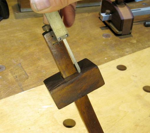
I do the resaw in three passes, raising the blade about a half inch each time, ripping both top and bottom edges. I first check the blade for exact squareness using a Wixey digital angle gauge and set up a feather board. If my saw had a bigger motor I could do this in fewer passes.

I always try to move my lunchbox planer to the driveway when thicknessing stock so I can clean up the mess with a leaf blower.  Since these boxes are destined to be unfinished gifts for small children, it’s not necessary to do a perfect planing job but any snipe or defective spots should be marked to go to the inside surface. Actually, in this cold weather, I have been planing most of the resawn boards with hand planes. It goes quickly and warms me up.

Once the 5/16″ stock is ready, the first step is to mitre one end. The saw blade is tilted to 45 degrees measured with my digital Wixey (love that thing) to satisfy the third condition above, and raised through an aluminum insert for zero clearance.  Note this is a left tilt saw.

Stock is positioned on the right side and aligned using the tilted fence kerf to cut the first bevel. The stop is lowered and adjusted for this set of boxes so the outside measurement to the blade is 8 1/2″.

0892

Move the stock to the left side and make the second cut by holding it against the lowered flip stop. This completes the first long side.

0825

Raise the stop, return the stock to the right side, and make a new initial bevel as before. The cutlist measurements are tight so it’s necessary to cut exactly on the previous bevel line.

For the second cut the spacer block is placed against the flip stop to create a 2 7/8″ end piece.

0896

Repeat the above two operations to create another long side and another short end piece.  Cutting out the four sides of a box takes only a couple of minutes once the initial setup is done.

0899

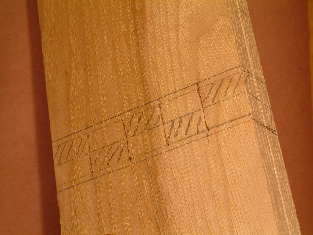
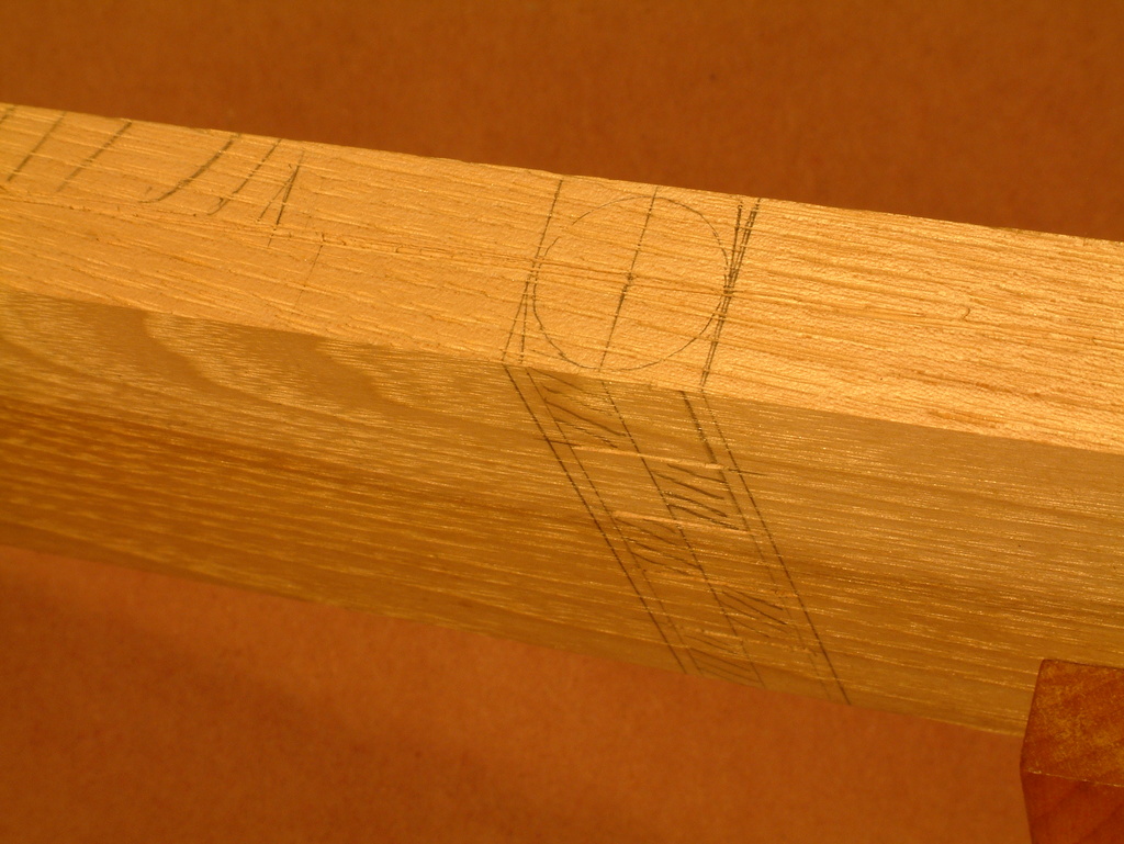
Cutting box sides sequentially from a single board lets the wood grain wrap around three of the four corners, a nice touch. To make that possible, the box has to be ultimately glued up in the same order as it was cut.  Turn the pieces in order bevel side up and mark each beveled edge with it’s mate. If you make marks on the bevel near the center, they won’t show when the box is assembled.  Use a dark Sharpie so you can see the dots through a layer of glue, (but not too dark, I found sometimes the Sharpie bleeds through to the outside face). In this photo, see a one dot corner and a two dot corner for box #5. Note how the grain flows through the three pieces.

0804

Care in squaring the fence, setting the blade angle, and using a solid flip stop is rewarded with perfectly closed corner joints.

0788

Finish the six box components by cutting out two plates for the top and bottom. Return the thin kerf blade to vertical, adjust the stop for an 8 1/8″ cut and make two pieces. That little bit is all that’s left over from one of the 40 inch boards.

0810

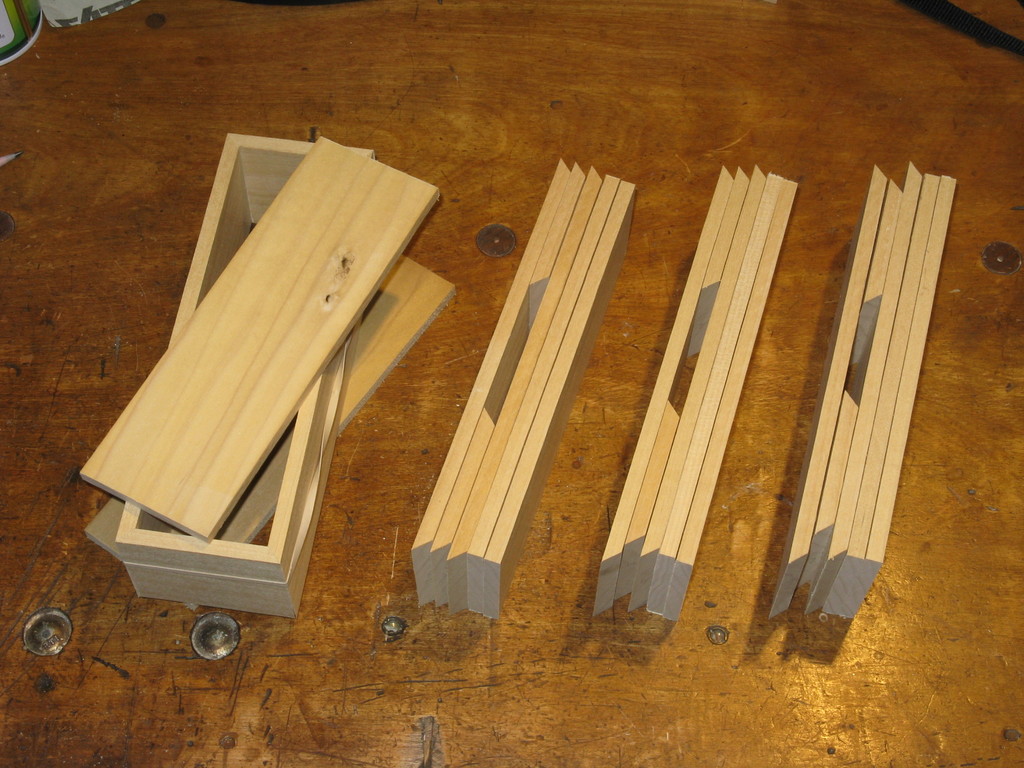
Here are four box kits ready for grooving.

0790

Next, set up the table saw to do eighth inch deep grooves at the top and bottom of each side piece. The same setup can be used to make eighth inch rabbits around the top and bottom plates.  I use a 1/8″ brass setup bar to help set the saw to just over 1/8″ height and spaced 1/8″ from the fence. The blade in the photo is one side of a Freud dado stack. It makes a clean cut and has the correct width.

0811

Roy’s video shows cutting the groove before slicing off the beveled side pieces. With the table saw it’s easier to do this after the sides are cut out.

Here I am grooving a long side using a push block.

0900

Grooving the short side. Have to be extra careful where you put your fingers.

0813

Now all four sides of each top and bottom plate get rabbited. You need an eighth inch tongue on each edge that makes a sliding fit in the groove around the box sides. It may take some fine adjusting of the spacing between saw fence and blade to get the fit just right. The plate should slide easily in the groove but not rattle around.

Hold the pieces vertically, pushing them across the saw blade. Cutting the tongue with a single eighth inch blade leaves a thin sliver of material on the inside edge of the top and bottom pieces. You can eliminate that by adding a second Dado blade on the saw arbor to make a kerf wide enough to remove all the wood.  Or just break off the sliver.

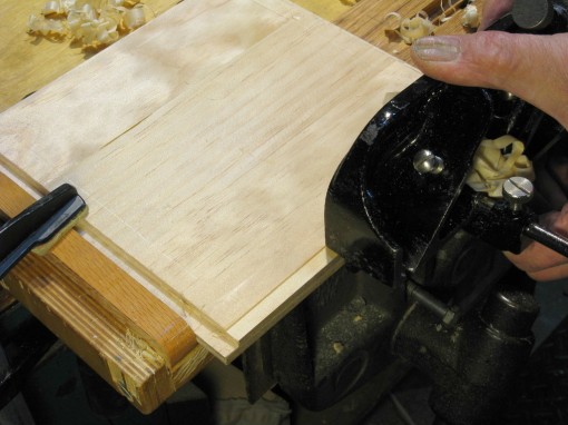
Here I have added a tall fence to help guide the lid plates, and I’m using a push block for the end grain cuts. Even with the push block, the piece tends to wobble and cut unevenly, so I usually make two passes to make sure the rabbit is full depth. It’s best to do the short edges first, then the long edges.

0815

Rabbiting the long side is straight forward. Again, fingers are close to the blade so extra care is needed.

0814

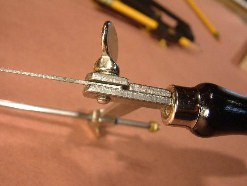
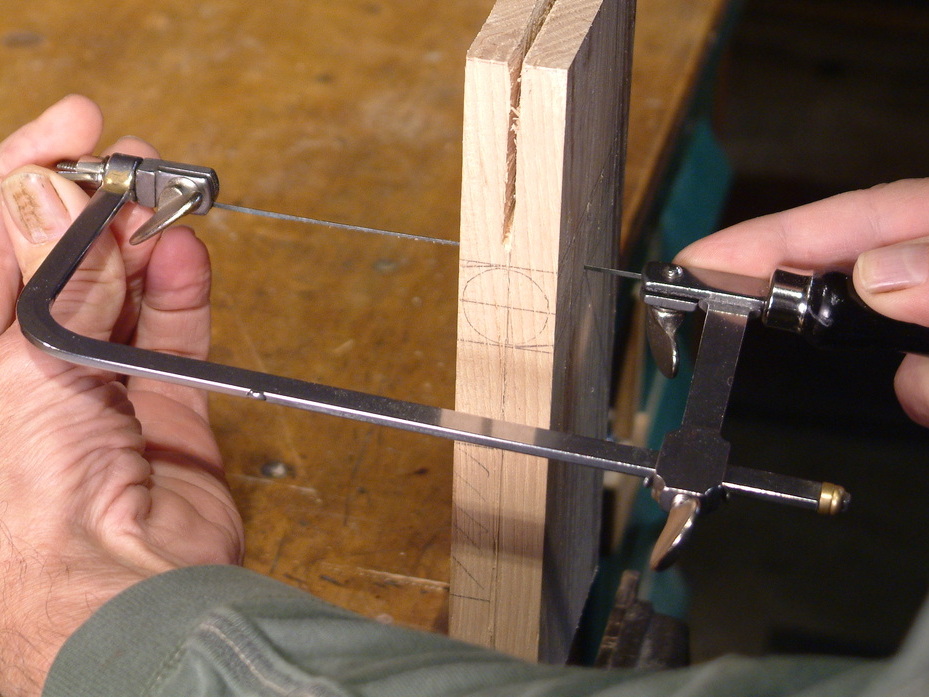
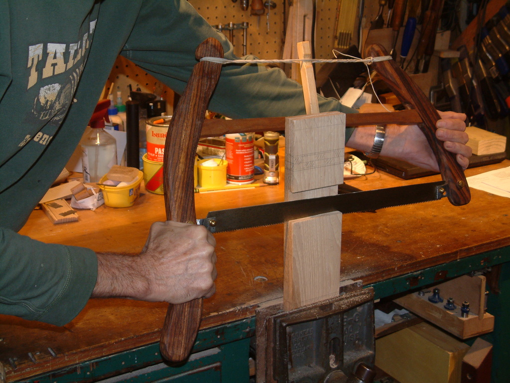
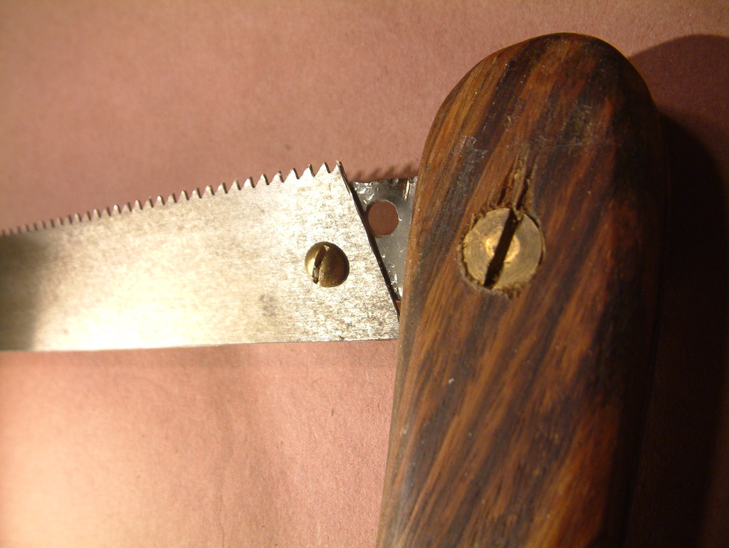
The final milling step is to mark and slice one of the ends off a half inch down. I do this in an old fashioned wooden miter box with a saw that makes a fairly thin kerf. Pick the end that has the grain wrapping around both sides, this should be the end piece with one dot and two dots. You can clamp a stop block inside the miter box to speed things up if there are many boxes to cut.

0817

Here is a completed set of pencil box components.

0793

Finally the glue up which takes more time than cutting out the parts. Use a long open time adhesive like Liquid Hide Glue or Titebond III. I apply with an acid brush that has half it’s bristles clipped off to make it stiffer.

Here’s all my gluing tools. Bottle cap to hold a puddle of Titebond or LHG, wood stick wrapped with damp towel to clean grooves, cut down acid brush, burnisher to close corners, thin snap knife to cut lid handle free if it’s gotten stuck from squeeze out. The tools are sitting in a two sided tray I use to hold the box while assembling the parts.

0819

Roy says to rubber band the parts so I made Red Neck glue clamps from something I have a lot of, punctured bicycle inner tubes.  Just slit a length of tube top and bottom. They will stretch about 25% so make the slit an inch or so shorter than the box. It helps if you use the two sided tray to corral the box parts while you’re stretching the rubber over the outside.

A 45 degree miter will be half end grain. To get good adhesion, I paint glue on the bevels in two stages,  I give each a first coat to fill the wood pores, then after a minute, another coat to do the joining.  Try not to get glue in the corners of the eighth inch grooves, it will stick the lid plates in place and you don’t want that. Make a groove cleaning tool by folding a damp paper shop towel around the end of a putty knife. Do NOT apply glue to the bevel area at the box front where the half inch handle will go.

Put the box together by inserting the top and bottom plates in the two long side pieces first (watching those Sharpie dots), then press on the end pieces. The half inch handle is not glued at this time but do put it in place to help shape the rest of the box.  Apply two Red Neck rubber band clamps, then fuss the side corners to get good miter alignment.  Also check that the miter joints are aligned vertically so the top and bottom edges are all in the same plane.  It doesn’t take much of a vertical mis alignment to make the sliding lid hard to seat. Finally check with a small square to see if the corners are 90 degrees.

Allow a few minutes for the glue to take hold, then pull the half inch handle off.  Slide the top plate out. If it won’t budge, you have squeeze out on the back corners. Get a pair of pliers and wiggle the lid until it lets go. Now apply glue to the end of the lid that will receive the handle. Press the handle on to the end of the top plate, centering it on the plate and clean up any squeeze out on the bevels.  Place one or two thicknesses of paper towel in the groove at the rear of the box top. This will force the lid plate into the handle groove. Push plate and handle back into the box against the paper towel, making sure the handle seats properly against the box sides. Slide the rubber band up over the handle.

0802

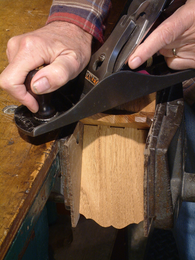
Remove the Red Neck clamps the next morning, sand off any glue squeeze out, and lightly break sharp corners and edges with fine sandpaper. If there are any gaps in the miters, you may be able to close them by burnishing the two edges. The lid should slide smoothly. If it doesn’t, tune with sandpaper or a shoulder plane. For extra credit, plane the top and bottom edges flat. I use a 5 1//4 for this, the bed is long enough to use the opposite side of the box as a reference surface.

0823

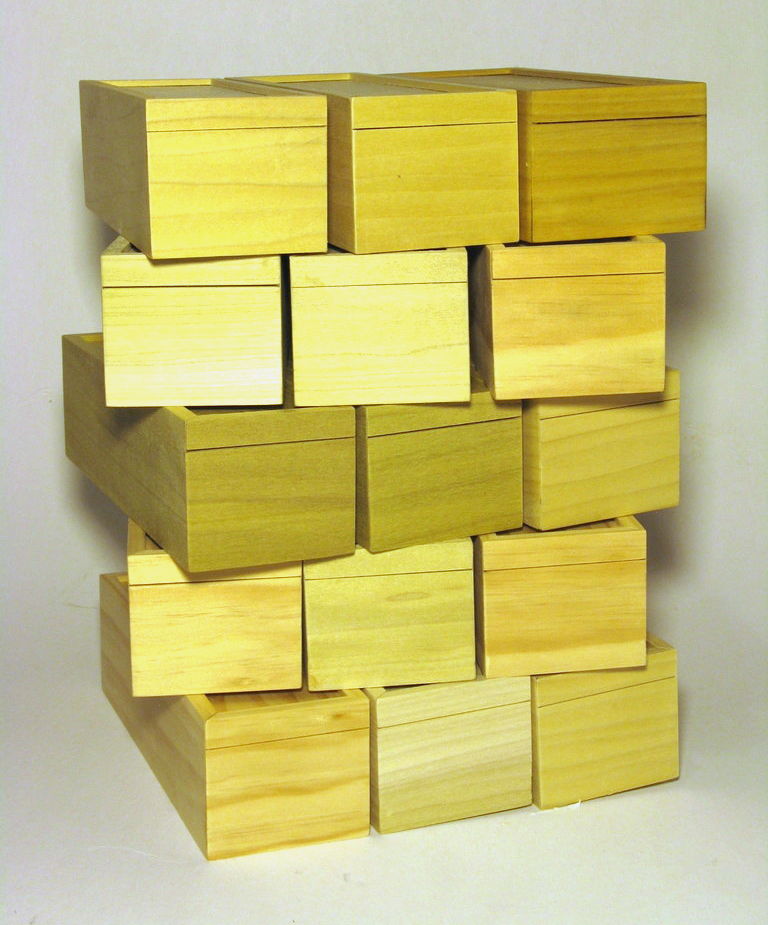
This has been a very satisfying project. Thanks to Roy Underhill for the inspiration. Here is the first crop in Poplar and Pine from Menards cut off bin.

0820

Update 12/26/16

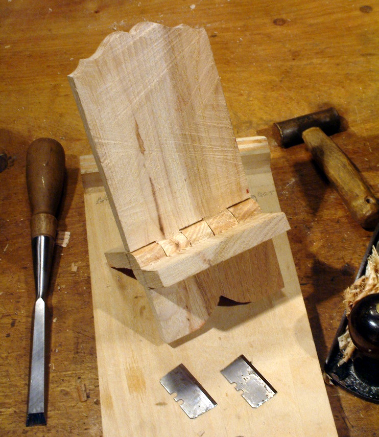
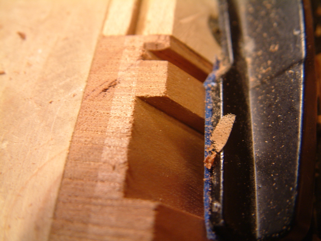
I had a few of the lids stick hard due to squeeze out in the back corners. Had to pull them out with pliers which runs the risk of damaging the wood. Now I’m nipping about 1/3 of each corner off with a chisel which gives squeeze out a place to go. I don’t nip the front corners of the top lid where it will be fitted to the handle piece.

0828

Update 2/1/17
I typed up the page of arithmetic for sizing the box parts. Also made a spread sheet to do the calculations. All this and more is in this zip archive.

Update 2/11/2017
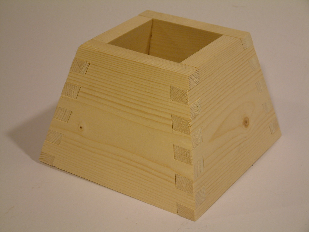
Trying an alternate design. These 4″ x 4″ x 4″ cubes are each made from a 24 inch piece of 4″ by 5/16″ stock which was ripped and resawn from a 1×10. Since the sides are square, I don’t need a spacer. Also learning more about Titebond Liquid Hide Glue, you do need to paint on two coats or the joint will be weak. And I’ve found that a small amount of warp is tolerable, because cutting the stock into short pieces means the warp in each piece is small. Warp can complicate resawing though, and if the board is cupped, you will have trouble with the glueup. A cupped board will not allow an accurate miter unless it’s forced down flat on the crosscut sled.

I made these 12 in one afternoon, glueups were done the following morning in the house where it’s warmer. I cut up my last bicycle inner tube to make shorter redneck clamps, using a paper punch to make a hole at the ends of each slit which should reduce strain at that point.

0840

Update 2/20/2017

Revised some photos and text to emphasize use of a crosscut sled. It really does work better.

Update 4/3/2017

Nineteen pencil box sized “kits”. This batch was made from steeply discounted lumber and will bring my count to 110 boxes. I think that’s enough, I’m running out of places to put them.When I go through the production process I line up all the box parts on the bench to keep them together. After the last operation each is rubber banded into a package ready for glue. It’s still too cold to work liquid hide glue in my garage so these will be finished in the house.

And here are the 19 pencil boxes assembled, sanded and ready to go.

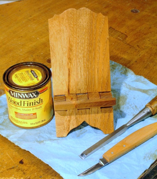
Also built several mongrels out of scrap. Making a box from bits of different boards has it’s own set of problems. I’m keeping these two and applying three coats of Watco oil.

Update 5/13/2017

I can’t stop making these things. Over 130 now. This batch is mostly mongrels, made from scraps but the four cubes on the right came from a single 24 inch 1×10 from Menards’ cut-off pile. The board was was $1.75 so less than 50 cents per box.  Two Cherry cubes on the right have a center divider, both lids slide open. I’m keeping and finishing that nice grained Yellow Pine bottom center, and some of the Cherry boxes.

Update 11/18/2017

I’m presenting my methods to the Dupage County Woodworkers Club next week and since I can’t fit a table saw into my car, have created a slide show.

It is downloadable from dropbox at https://www.dropbox.com/s/c67c4xhlw3bata7/SlidingLidBoxes.zip

The miter sled is upgraded to a real TTrack and there is a different setup for making the grooves. The calculations are now done with a spreadsheet. The most recent version of the spreadsheet is  https://www.dropbox.com/s/xdry4hyrbqg95a8/TriangleBoxes.zip?dl=0. It has sections added for hexagonal and triangular boxes.

Update 05/17/2018

The spring 2018 episode 35 video from Highland Woodworking, about 22 minutes in, shows Doug Stowe creating mitered corner boxes using a crosscut sled and spacer block in a manner similar to mine. His method does not require a flip stop though.

Frame and Panel Construction – Part 1: The Panel

These WordPress pages document my method of constructing a frame and raised panel door. I need to make a pair of these about 30″ x 18″ each to replace an ugly entrance to the crawl space in my home. Each door will be a single solid Pine panel, the frame will be about 2 inches wide with molding on the inside edge.

One episode of “The Woodwright’s Shop” contributed to my panel raising techniques. “Raising Panel-Zona” describes several methods, though my tools don’t match Roy’s.

I have a small panel raising plane. It is unusual in that it has an adjustable fence, there is no nicker and no flat area near the fence, the cut is beveled all the way to the edge of the work. It may have had some other use in the past but it works for panel raising. I have since added brass strips at the main wear points.


Making a cabinet door usually proceeds by constructing the outside frame to fit the target opening, then creating a panel to fit the frame. I have a number of frames made as practice exercises for a real job closing off the crawl space in my house. These were all based on square blanks cut from a length of 1×8 select pine from Home Depot. I used up all the spare lumber so for this weblog post I glued up some scraps and trimmed to 7 1/4 square.

Panel blank glued up and trimmed to size

Panel blank glued up and trimmed to size


The panel will have a quarter inch tenon all around the edges that seats inside a groove plowed around the inside edges of the frame. The first step is to define this tenon edge by measuring the frame face to groove distance so the panel  will be flush with the frame. Subsequent operations will remove wood down to these lines. I darken the marked lines with pencil.

Mark the tenon edges on the panel blank

Mark the tenon edges on the panel blank


The panel raising plane fence has been set to an “about here looks right” distance from the cutter tip. I’m measuring this horizontal distance carefully, maintaining the angle of the bevel.

Measuring horizontal length of the bevel cut

Measuring horizontal length of the bevel cut


I will be defining the inside line of the raised area using a cutting gauge. This is necessary, especially on the cross grain sides because the plane does not have a nicker. Here I transfer the measurement from the previous step to the gauge.

Transfer bevel dimension to cutting gauge

Transfer bevel dimension to cutting gauge


Cut the gauge lines deeply into all four sides of the panel blank.

Cutting bevel extent lines

Cutting bevel extent lines


Here I have darkened the lines with pencil.

Bevel lines darkened

Bevel lines darkened


One hand tool principle I have learned well is to remove as much material as you can with the blade that is easiest to sharpen. I block plane off wood down to about 1/16 inch from my two lines.

Removing waste wood

Removing waste wood


Now the panel raising plane does it’s work, starting with the cross grain edges. This plane works well across the grain because it has a steeply skewed blade. Which also means it is hard to sharpen.

Using the panel raising plane

Using the panel raising plane


Raising the center creates a shadow line which makes the panel look a bit smaller and lighter.

Panel showing shadow line

Panel showing shadow line


The final step is rabbiting the back of the panel to the line. This M-F 85 has the fence set to cut a quarter inch wide relief and the depth stop set to stop at my line. Since the raised portion of the panel is angled, the edge tenon is tapered so I will make this a little less than a quarter inch thick to make it easier to fit the frame groove.

Rabbiting the back side

Rabbiting the back side


The finished panel came out fairly well though I had trouble with the panel raising plane. I believe the blade is not bedding flat inside the body which causes the blade to flex slightly and chatter. The wedge also loosens too easily which causes the blade to fall out. I’m working on it.

Finished panel

Finished panel


And it does fit the frame. See how all those shadow lines make the panel look like something other than a flat board.

Finished panel fitted in frame

Finished panel fitted in frame


Frame and Panel Construction – Part 3: The Real Thing

Parts one and two of this series showed construction of a small frame and panel assembly. I made a half dozen of those as learning exercises for the final project, rebuilding the entrance to the crawl space in my tri-level home. This may be way over engineered but the old doors are truly ugly, made from thin paneling covered with contact paper, and besides, I wanted to learn how to make raised panels with hand tools.

Most of the techniques I used came from the Woodwright’s Shop episodes mentioned in part 2, this part 3 will document differences needed to complete the larger scale crawl space entrance.

I built a new outer frame from 2 inch pine to fit the existing opening.  I have to admit not using hand tools for that as I recently acquired a Kreg K2 jig and wanted to try it out. Also the rails on a butt jointed frame would be four inches shorter than a mitered corner frame which worked out much better with the 72″ stock I had.

Pencil study for cut list

Pencil study for cut list

The outside dimension of the doors is determined by the inside edges of the outer frame so I propped up the outer frame and centered the stile pieces leaving about 1/16″ gap at the sides.

Outer frame with door stiles

Outer frame with door stiles

Each pair of stiles was checked for parallel with pinch rods. Everything came out OK with very little tweaking. Stiles were marked top and bottom where they touched the outer frame.  Then I centered the rail blanks on the stiles and marked where they touched the rails left and right. Those four lines define the dimensions of the doors.

Checking stiles for parallel

Checking stiles for parallel

Here you can see tenons laid out on the four rails. These were sawn, tuned, and outlines transfered to the stiles as in part 2. Mortising the stiles, then grooving and molding the inside of each piece proceeded as in part 2.

All four rails with tenons laid out

All four rails with tenons laid out

I glued up two panels a couple months ago but had to square them for fitting in the frames. Could not hold the panel steady against the miter gauge so I built a miter gauge helper from a piece of heavy aluminum angle and a toggle clamp, should have done that years ago. The panel surfaces were planed with a Stanley 4 1/2.

Straighten and square the panels

Straighten and square the panels

Each completed door frame was laid over the square glued up stock. I aligned left and bottom panel edges with the inside of the frame, marked the top and right edges of the inside opening on the panel stock, then ruled a line one half inch farther out on the top and right. This allows room for a 1/4″ tenon all around the finished panel. I then trimmed the panel top to my ruled line on the table saw using the miter gauge as in the previous photo.

Next, the panels had to be trimmed to width. They are too tall to use the miter gauge, so I got out my standard homemade saw fence, a four inch oak timber. I used the line on the cut off top piece to adjust the fence to the proper width.

Setting fence to rip long side of panel

Setting fence to rip long side of panel

A deep breath moment.  I had been putting off cutting these panels to exact size because I was afraid of screwing up the measurements. In the end, they fit well.

Panel ripped to final width

Panel ripped to final width

As in part 1, I struck a line with a cutting gauge to define the panel step, then removed wood with a block plane to 1/16″ of the line.  Raising the panel actually means lowering the edge. It depends on your point of view. In this photo, the cross grain ends have been lowered and I’m ready to work the long grain edges.

Roughed in panel bevel

Roughed in panel bevel

The panel raising plane lowered the bevel to the edge line and created the top step as in part 1. This took a while as the panel raising plane was acting up and I took time to tune it. I believe the bed under the blade is not flat so the blade doesn’t fit properly.

Completed raising of both panels

Completed raising of both panels

There were a LOT more shavings than in part 1. Working the two panels took most of an afternoon.

Shavings from panel raising

Shavings from panel raising

The last operation on the panels is creating a rabbit all the way around the rear side. Always cut the cross grain ends first then the long sides. Knifing the cut line with the gauge is mandatory on the ends, the spur on this MF 85 sticks out way too far. I also used a sharp knife to relieve the wood at the left end of the rabbit before planing to reduce tearout there. There was a small amount of fuzz which I cleaned up with the wooden shoulder plane.

I had more trouble with the sides than the ends, the grain was not with me. Home Depot pine does not have a strong grain pattern and it’s hard to see how it’s running. Waxing the plane about every fifth stroke helped.

Rabbit the back side of panels

Rabbit the back side of panels

Checking the tongue for fit in one of the rail piece grooves. I want a good fit to keep the panel from rattling around if it shrinks. I found a web site that calculates wood movement, these 14 inch wide panels could move with humidity variations as much as an eighth of an inch.

Test fit of panel with one of the rails

Test fit of panel with one of the rails

Finally, the completed panels fit with very little tuning. I sawed off the frame horns and am happy with the results. This photo shows the back side of the assembled doors.

Rear view of panels assembled into frames

Rear view of panels assembled into frames

And this is the raised panel side.

Front side of assembled doors

Front side of assembled doors

The sawn off horns were rough so I converted my workbench and planing fixture into a shooting board.

Shooting a top edge

Shooting a top edge

Checking the frame and panel doors for fit in the frame is awkward as I don’t have an area in the garage that I trust to be flat. I had to trim 1/16″ from the left bottom, the rest fit well. There will be a final tweaking after the hinges are installed, and a final-final tweak after the glue up, and a final-final-final after it’s nailed onto the crawl space.

Checking the doors for fit

Checking the doors for fit

Hinge position is somewhat arbitrary. I used the bottom of the panel field as a reference. A steel ruler is held against the raised line and the outer frame marked. This sets the outer edge of the hinge gain.

Marking hinge position on outer frame

Marking hinge position on outer frame

Laying the hinge on the marked frame defines the inside of the hinge pocket. Both marks were squared across the inside with a knife and deepened with a chisel. I chiseled every quarter inch along the area to be removed then used a Stanley 71 to remove wood. Clamping boards to the sides gives the router plane has something to sit on.  A Stanley 71 1/2 that doesn’t have the wide gap at the front would work better for this.

The hinge plate measured .060″, I cut the pockets to about .080″deep to narrow the gap between door and outer frame.

Routing a pocket for the hinge

Routing a pocket for the hinge

I use a small Vix bit to establish the hinge screw position then pilot each hole with a 1/16″ drill so the screw doesn’t wander in this soft pine grain.

All four hinge gains were cut in the outer frame, hinges screwed in, then the doors were re-inserted and marked where the hinges touched. Those marks were knifed square across the outer stiles and incised with a chisel.

Preparing to seat a door hinge

Preparing to seat a door hinge

I was able to clamp my router support fixture on the doors. It forms a reference surface for the router plane and also furnishes a square outer edge to locate the hinge.

Router support fixture

Router support fixture

Here the hinges are seated and the doors dry fitted back in the outer frame.  The doors closed OK with a small amount of planing on the inside vertical edge. There will be a final fitting after the door frames are finished and glued up.

Completed frame with doors dry fitted

Completed frame with doors dry fitted

Tenon cheek cutoffs are perfect for trying out different finishes and I have 16 of them. I made several samples using Minwax Jacobean, Dark Walnut, and English Chestnut stains plus a few samples with various mixtures. I also experimented with Minwax Pre-Stain Conditioner which produced much more even results. Most of the wood in the house near the crawl space entrance is very dark and I thought the Jacobean would be the best match, but the wife overruled and picked the English Chestnut sample which is much warmer.

The doors were removed and completely disassembled for staining. A raised panel can not be finished in place because if it shrinks, an unfinished area would appear at the edge. So at least the stain has to go on with the panels outside the frames.  I did separately the door frames, then the panels, then the outer frame as I did not want to let the stain set too long without wiping off. The Chestnut stain did not color evenly though the conditioner did help. This photo shows the two door frames, one of the panels and the outer frame.

Stained doors

Stained doors

With every frame piece stained and both panels stained all the way to their edges, it was finally time to glue up the doors. I dry fitted the everything together again, reattaching the doors to the outer frame with the four hinges for a final fitting.  I noticed the hinge screws were loosening up after being removed three or four times so following a tip in a recent magazine, I drizzled super glue into the screw holes. It seems to help quite a bit.

I propped one door open, removed the center stile, pulled out one rail at a time, applied liquid hide glue to the hinge side tenon and plugged the rail back into the hinged stile. Because I did one rail at a time, the panel could remain in place. Both rails then got the inside tenon buttered with LHG, and the inside stile installed.

Since the doors were still hinged to the outer frame I could check for racking before the glue set up. I clamped the doors in the outer frame, using thin wedge shims inserted under the hinges to even the pressure.  After 2 hours for the glue setting, I did the second door the same way.

Clamping the glued up mortise and tenon joints

Clamping the glued up mortise and tenon joints

The next day, I removed the doors yet again and took the outer frame to the crawl space for a fitting around the opening. A little dry wall trimming was all that was necessary. Minwax semi-gloss poly was next, two coats applied to each door and to the outer frame.

Panel with Poly applied

Panel with Poly applied

Check out the shadow lines in this photo.

Detail showing frame molding

Detail showing frame molding

There were a bunch of cutoffs from ripping original stock down to two inches. I planed, stained, and varnished some of them.  These will form a lip around the inside of the crawl space opening. One of the original specifications was that the doors be insect proof.

Cutoffs to be used as seals

Cutoffs to be used as seals

Finally it was time to install the frame and assemble the doors.  There are only four 8d finishing nails, one at each hinge, holding the frame on in this photo. I may put more nails in the top and bottom rails after the wood acclimates but for now the doors close without rubbing anywhere. One of the finished strips was screwed to the inside edge of the left door with a quarter inch protrusion, so the right door holds the left door closed and theres no visible gap. The old doors had two magnetic catches, I reused one at the bottom of the right door.

Installed!

Installed!

This is what it used to look like.

Crawl space entrance Before

Crawl space entrance Before

This has been a four month long project with much of the time spent learning how to use hand tools to create the raised panels. I couldn’t have begun without inspiration and education from Roy Underhill. Three episodes of “The Woodwright’s Shop” contributed to the project.
Raising Panel-Zona” describes several methods of making a raised panel.
Painless Panel Doors” where Roy constructs a mortise and tenon frame.
Simple Sash Restoration” shows how to join a frame with molding around the inside.

Automating the Box Joint Jig Lead Screw

I constructed an Arduino based controller to automate the carriage on my lead screw Box Joint Jig which was originally inspired by Matthias Wandel at woodgears.ca. Interestingly, Matthias added automated operation by a laptop to his design at the beginning but later removed the function in favor of multiple wooden gear sets. My jig was manual at first and automated later after I kept losing count of the crank turns

See this WordPress Blog entry on construction of my Box Joint Jig and also this Blog entry on some of the applications.

A video of the development breadboard in action is at www.youtube.com/watch?v=6Zz1fGDO5jw.

A video of the controller installed on the jig and working is at www.youtube.com/watch?v=URk4qYnEWgI

I used an inexpensive DC motor driven with a Polou MD01B H bridge, and added position feedback to the lead screw. This gear drive motor from All Electronics (DCM-697), was intended for actuating automotive power seats.  I sawed the shroud off the connector housing so I could use standard push on terminals.  The mounting base is a bit of hardwood flooring rounded out to fit the motor and hose clamped on. I can loosen the clamps and slide the motor to align the sprocket and adjust the chain.

Modified Power Window Motor

Modified Power Seat Motor


This shot shows how the lead screw shaft has been cut and ground down to fit the "D" shaped hole in the drive sprocket.

Window Motor Shaft

Seat Motor Shaft Ground Down


Two 24 tooth sprockets from All Electronics (GR-100).  They don’t come with a cap for the shaft collar so I made some from a piece of aluminium. Normally they have a “D” shaped hole. The sprocket on the left has it’s D intact – it will go on the motor shaft. The sprocket on the right has it’s D filed out round so it can clamp on the 3/8 threaded rod that drives the Box Joint Jig.  I have since replaced the motor side sprocket with a 42 tooth part to speed up the carriage motion.

24 Tooth Sprockets

24 Tooth Sprockets


Photo of the first test bed.  Power seat motor on left, Pololu motor driver (MD01B) above that, protoboard in the center and Arduino on the right.  Two buttons on the protoboard run the motor either CW or CCW.  The amazing little Pololu board has a VNH3SP30 H bridge chip which is less than 3/4 inch square but can switch 30 amps!

Bare Test Bed

Bare Test Bed


Since the motor is a simple series type, I need a way to inform the Arduino how far the shaft has rotated.  An optical sensor could be used but then there would be sawdust issues. Instead I use a Hall Effect sensor and permanent magnets.

This is the prototype position disc. It will go on the jig’s lead screw.  Quarter inch button magnets are coupled to six penny nails to focus the magnetic field and pressed into slots sawn in the disc.

Prototype Feedback Disc

Prototype Feedback Disc


Here the magnets and nails have been epoxyed and a coat of varnish applied.

This was intended to be a prototype but performs well enough that it probably will be the final.  The disc is 3 inches in diameter and will be taped directly to the motor sprocket for software development purposes.

Trimmed Magnet Disc

Trimmed Magnet Disc


Detail of the disc edge showing one of the six penny nails sawn off and filed flush.

The Hall Effect sensor (SS441A from Jameco) gives a clean transition when placed about a quarter inch from the edge of the disc. NO bounce observed (Yay!) so I can easily code an interrupt driven counter. Eight steps per rotation on the 16 TPI shaft will give a resolution of  0.0078125 inch at the carriage. One – One Hundred Twenty Eighth of an inch.

One of the Magnetic Poles

One of the Magnetic Poles


Since this is the Breadboard phase of development, I thought it appropriate to mount the parts on a real board.  At this point the motor software is done but the menus are not. A video of the development breadboard in action is at www.youtube.com/watch?v=6Zz1fGDO5jw.

Clockwise from the top:
– Chain and sprocket for the lead screw
– Sensor disk temporarily on motor
– Motor and mount screwed down now
– Hall Effect sensor glued to a stick
– Stick clipped to mount so its adjustable
– Arduino clone board
– 16×2 LCD display
– PWM pot (not used, will be removed)
– Proto board with LEDs and buttons
– MD01B motor driver

Final Development Breadboard

Final Development Breadboard


Here is the box I selected to hold the completed controller.  It is a standard electrical box from Lowes, but it has a bump out on one side that forms a nice surface on which to mount button switches. The lid of the bump out is molded as part of the box. You fold it over and it snaps on. You can do this about 3 times before the plastic hinge breaks off so plan the layout carefully beforehand. 30 Cubic Inches sounds like a lot until you start stuffing cables in there.

I amputated the 8 penny nails and mounting ears.  LCD and LED indicators mount flush on the top where the AC receptacle would normally be.

Electrical Box

Electrical Box


I think the box has enough holes now….  Putting the controller hardware into the box is more complicated than it seems. Just the box itself needs wires from two buttons, power switch, 12 volt feed, motor feed, two limit switches, and the Hall Effect sensor.

Outside, a blue Euro style block is glued on for the Hall and limit wiring, Two pin Molex connectors added for the 12 volt leads.  The box material is soft enough that it cuts easily with a utility knife.

Box With Wiring

Box With Wiring


Here is the Pololu MD01B motor driver in it’s new home. Have to use plastic screws because the plating around the mounting holes is electrically hot (why??).  This small sheet of aluminum fastens inside the box via the two countersunk holes visible just above the buttons in the previous photo.

Pololu MD01B Mounting

Pololu MD01B Mounting


The Arduino clone processor is mounted on the opposite side of the aluminum plate.  Four analog inputs and 12 digitals are cabled out.

Arduino on Mounting Plate

Arduino on Mounting Plate


Four LEDs and the 2×16 Liquid Crystal display are mounted on a piece of plexiglass cut to fit the top opening of the box.

Leds are:
slewing left
power on
hall sensor (added for coolness factor)
slewing right

Display Panel Front

Display Panel Front


This is the display panel seen from the bottom.  Four 2 wire connectors for the LEDs and a 10 wire cable for the LCD display.

The small connectors are salvaged from PC front panel displays, the multi wire connector is sawn off an IDE hard drive cable.

Display Panel Rear

Display Panel Rear


I used a Radio Shack PC board to make a central interconnect for all the buttons, limit switches, LEDs, Hall sensor, LCD display, and processor.  There is a 5 volt regulator for the logic side, pullup resistors and LED dropping resistors.  This cries out for a printed circuit board but since I’m only building one of these, it will do as is. I would have to work through this stage to design a PC board anyway.

Interconnect Board

Interconnect Board


Made a drawing of the interconnect board so I could remember where things plug in.

Interconnect Board

Interconnect Board


Final mock up to test wiring. All this has to go into the blue electrical box. Found two LEDs functionally reversed. One of the cool things about the Arduino is the pins are software defined so that took maybe a minute to fix in software. The 5 volt regulator got too hot for comfort so in a last minute change, I moved the regulator chip over onto the aluminum sheet – even more wires!

Final test Before Assembly

Final test Before Assembly


Well it does all fit, though it’s a PITA to find a place for all those wires.  This shows the completed controller connected to the breadboard motor mount having just made a 128 step (1 inch) simulated slew, sixteen revolutions of the sensor wheel.  Those two microswitches will be limit switches on the jig, and I will use an inline fuse in the 12 volt feed, couldn’t find room inside.

Testing Controller on the Breadboard

Testing Controller on the
Breadboard


This shows the motor screwed to the end of the jig, two sprockets, and #25 chain. These parts came from All Electronics.

It sticks out more than I hoped.  Maybe need some kind of guard to keep fingers out of the chain.

Motor as Mounted

Motor as Mounted


I made a small L shaped plywood structure for mounting the controller on the box joint jig.  The mounting is tall enough to protect the sensor wheel assembly and the right limit switch.

Controller Mounted on Box Joint Jig

Controller Mounted on Box Joint Jig


Mounted the left hand limit switch horizontally. It is very exposed so I cut off most of the actuating lever and made a guard out of aluminum.

Left Limit Switch

Left Limit Switch


This photo shows the sensor wheel mounted on the lead screw shaft. The Hall Effect sensor is epoxied into the small wood block just right of the wheel.  It gave me grief, it didn’t work!  After a lot of experimenting, I determined the Hall sensor is only sensitive on one side. I had glued it into the block upside down.  Turned it over and success!  You can also see the right limit switch mounted vertically.

Sensor Wheel

Position Sensor Wheel


I set the controller to slew sixteen inches. Ran it up and back about ten times, it always came back to the exact same spot.  Takes more than a minute to go 16 inches.  I will look for different sprockets to speed it up. The motor has plenty of torque, I put most of my weight on the carriage and it didn’t slow down a bit. I’m using an XBox power pack to supply 12 volts, it’s easily up to the job, but wish I could figure out how to get it up to 15 volts.

A video of the controller installed on the jig and working is at www.youtube.com/watch?v=URk4qYnEWgI.

Sixteen Inch Setting

Sixteen Inch Setting

Arduino source code can be downloaded from Dropbox here.


Completed Box Joint Projects


A Roy Underhill Memorial Tool Tote.  About 30″ long, 9″ wide.  The yellow pine does not seem to take an oil finish well.

The box (finger) joints all cut on the automated lead screw jig.

Yellow Pine Tool Tote

Yellow Pine Tool Tote


Another smaller tool tote done on the automated jig. This example in Cherry.

Tool Tray in Cherry

Tool Tray in Cherry


These boxes made for my two Stanley 45 Combination Planes.

House for Homeless Stanleys

House for Homeless Stanleys


I made this to hold a small Variac transformer. Keeps my soldering iron at just the right temperature.

Variac Box

Variac Box


This Walnut, Butternut, and Oak box was made for my Brother-in-Law.

A Box for Johann

A Box for Johann


Compound Angle Box Joints

This is a practice piece for a larger project.  I wanted to make a tool tote like the one Roy Underhill carries in the introduction to “The Woodwright’s Shop”.  There is a description of the tray in Roy’s book “The Woodwright’s Apprentice”. His example is butt jointed and nailed together, but I thought it would be nice to do the tray with box joints and glue.  Thus started a journey into trigonometric hell.

Practice Piece

Practice Piece


The sides of this piece are 15 degrees from vertical (75 degrees from horizontal) which is close to Roy’s slope of 1 1/2″ rise over 5 1/2″ run.

The only other reference I had for compound joinery was a section in Tage Frid’s book “Tage Frid Teaches Woodworking, Book 1: Joinery” on hand cutting dovetails in a similar situation. Not for the amateur woodworker and difficult to follow.

Other references may be available – Google is your friend.

Strange things happen when you slope the sides of a box.  All the angles change and the side edges are no longer parallel.  People who install crown moulding are familiar with this.  I used the Butt Joint calculator at www.pdxtex.com/canoe/compound.htm.

To get the side and bevel angles needed for the project. It is easier for me to think of these angles as offset from vertical (90 degrees) so I entered 75 degrees as the side slope.

Compound Angle Calculator

Compound Angle Calculator


The table saw has it’s blade tilted to the calculated bevel angle (3.84 degrees) and the miter gauge tilted to the calculated side end angle (14.51 degrees from 90 or 75.5 degrees).

Cut the first edge with the miter gauge in the left hand gauge slot. It helps to label the faces as the small bevel angle is small and not obvious. The narrower face goes towards OUTSIDE of the pyramid. For my right tilt saw, the piece being cut off in this photo has it’s INSIDE face up in this photo. The next piece, on the left of the blade, has it’s OUTSIDE face up in the picture.

Compound Cut

Compound Cut


Now rotate the miter gauge 180 degrees and put it in the right hand slot. Flip the board over and make the second cut. The piece being cut off now has it’s INSIDE face up.

This method does not waste any wood, but every other piece has it’s face side reversed which may be a concern if you’re matching grain.

After all the pieces were cut out I ran them through the saw a second time with a stop block clamped to the miter gauge to ensure they were all the same width.

The final step in fabricating the four sides is to tilt the saw blade to the slope angle (15 degrees in this case) and bevel the top and bottom of each piece. I used the table saw fence to guide this, but watch out for kickback.

Second Compound Cut

Second Compound Cut


If the butt joint angles are cut correctly on the table saw, a straight edge held parallel to the top or bottom will show no gaps across the junction of two sides.

Joint Alignment

Joint Alignment


To dado angled box joints exactly parallel to the slanted top and bottom edges, the work pieces have to be held in the jig in the position they will occupy in the finished assembly.

I made two complimentary spacer blocks, one for the right edge of the work piece, and another for the left.  I first glued up a 3 inch thick blank from four pieces of 1×6 pine. This was trimmed and planed square.  Then I laid out the lines for the necessary slopes all the way around the block.

Angle Block Layout

Angle Block Layout


The next corner of the block.

I found it was easier and more accurate to lay out the lines by calculating and measuring rise over run rather than use a protractor.

Second Side of Angle Block

Second Side of Angle Block


This is the opposite corner of the block.  The layout lines go all the way around.

I made several of these blocks before I got the angles dialed in right.

Third Side of Angle Block

Third Side of Angle Block


The fourth corner of the prepared block. The next step is to slice the block along the layout line.

Fourth Side of Angle Block

Fourth Side of Angle Block


A Sketchup model of the jig spacer block.  Angles for this 15 degree project are 3.8 degrees on the long side, 14.5 degrees on the short edge.

The dimensions shown are approximate due to Sketchup limitations.

Sketchup Screenshot

Sketchup Screenshot


This shows me and Henry Disston dividing the block along the layout line. It’s easier than it looks.

For a good example of how to do this see www.pbs.org/woodwrightsshop/video/2800/2810.html where they slice veneer off a walnut block by hand sawing.

Splitting the Angle Block

Splitting the Angle Block


Here the two halves of the block have been smoothed, and pegs added so they will plug into my box joint jig.

Note the orientation. The block on the left will go against the jig on it’s square face. The block on the right plugs into the jig on it’s sloping face.

Two Setup Blocks

Two Setup Blocks


A view showing how the sloping faces of the spacers lay against the jig. One spacer tilts out 3.8 degrees and slopes 14.5 degrees left, the other tilts in 3.8 degrees and slopes 14.5 degrees right.

Side View of Spacer Blocks

Side View of Spacer Blocks


The dado stack has to be tilted to match the side angle. This aligns the slot with the top and bottom surface of the work piece. For this 15 degree side slope project, the angle is 14 1/2 degrees off vertical.

An additional complication is, now that the dado is angled, the slot will be slightly wider than the stack width. Box joints depend on the slot being exactly the same width as the pin, so the pin size has to be increased to match. For this 15 degree project, I added 0.012 shims to the dado stack and increased the pin cycle by 1/16 inch. It came out pretty close.

Wixey out the Angle

Wixey out the Angle


Finally the jig with spacer is ready for duty. Here one of he blocks is plugged into the lead screw jig carriage, the work piece and a backer board are clamped to the spacer and I am pushing through the dado.

Note the masking tape throat plate. The jig itself provides a throat for the Dado set, the tape just keeps down the sawdust.

Clamping the work piece at the necessary angle is difficult. I used tapered shims to get a straighter purchase for the clamps.

Clamping the Workpiece

Clamping the Workpiece


Since the stacked Dado set cuts a square bottomed slot, but the edge parallel fingers require a trapezoidal hole, there is a small triangle of material that must be removed from each of the slots by hand.

Here I am knifing the edge of the triangular area.

Knifing the Slots

Knifing the Slots


The small side of the triangular areas can be sawn.

Sawing

Sawing


One of (many) practice pieces showing the small triangular area at the top of each slot that must be removed. Here I have defined the triangle using a straight edge and utility knife, also the small side has been cut with the dovetail saw.

DSCF0324


Now to remove the waste from the triangular area with a paring chisel.

It might be possible, if thinner stock is used, to build a fixture and do the clean out with a 14 degree dovetail router bit. If I had to do a lot of these I would investigate but it doesn’t take long with a sharp chisel.

Paring the Slots

Paring the Slots


Not a bad dry fit.  The material is cupped a bit which left some spaces but I think it will pull together with sufficient glue clamps.

The sloped sides are going to be a problem on the glue up.  I will make some 15 degree cauls to keep the clamps from sliding off, also will use strap clamps.

Practice Piece

Dry Fit Practice Piece


Finished Compound Angle Projects


This is the finished Roy Underhill Memorial Tool Tote created with the compound angle box joint jig.

First Tool Tray

First Tool Tray


Close up of the compound miter box joints on one end of the tool tote.  I don’t have all the cool hand tools Roy has so this project was built with machines.

Corner View

Corner View


Detail showing how the handle is mortised into the end pieces. Just like Roy’s.

Handle Detail

Handle Detail


This is a smaller tray in Cherry.

Tool Tray in Cherry

Tool Tray in Cherry


This was the last one I made, in Yellow Pine from Home Depot stair treads. The bottom is nailed on the sides, I covered up the finishing nails with copper carpet tacks.

Yellow Pine Tool Tote

Yellow Pine Tool Tote

Notes on the Roubo Bookstand

A Roubo Bookstand is made from a single piece of wood. It opens as pictured or folds flat. The design is actually much older than Andre Roubo (he wrote in the 1770s), it is a traditional form for supporting the family Quran.  Searching the Internet for “Roubo Bookstand” will keep you busy for many hours.

Here is plate 331 from Roubo’s book.

Plate331

Plate 331 from “L’Art Du Menuisier”

The project is based on a “Woodwright’s Shop” episode from season 31, 2011-2012. Many thanks and credit go to Roy Underhill. You can view it here or here  and you should to fully understand the material in this post as I won’t show steps here that duplicate Roys.  There is a downloadable plan here which references an almost identical book stand in episode 2205 which aired in 2002. The PDF plan differs only from the more recent show only in the shape of the hinge pockets. A much earlier episode, 1986 Season 06 ep. 3 has an example similar to the plan, using straight cuts for the hinge pockets, also see Season 20, ep. 5.  Woodwright’s DVDs are no longer available, but you can view them with the Popular Woodworking streaming service.

I’ve made this my hand tool project for 2014 and done several in soft wood for practice. In this web page I document methods and tools, especially where they differ from Roy’s.

I used construction grade 2x4s or 2x6s for practice pieces. The 2×6 version makes a fine Roubo IPad stand, the 2×4 size makes a dandy Roubo stand for a cell phone.

Roubo Tablet Stand

2×6 version Roubo Tablet Stand

Roubo Book Stand

2×6 version with a 7 inch tablet in place

I use this stand every week watching “Ask an Engineer”.

2x6 Stand with Nine Inch tablet

2×6 Stand with Nine Inch Tablet

I don’t own a smart phone but I borrowed one for this photo of the 2×4 version.

2x4 Roubo Cell Phone Stand

2×4 Roubo Cell Phone Stand

In the the next picture you can see two modifications I made to Roy’s plan. Both changes make the stand sit more upright making reading easier, and less likely to tip over. I shorten the front feet about 25%, and also inset the hinge pockets a bit, 3/32″ on this one inch thick stock. That keeps the stand from opening to a full 90 degrees.

Roubo Bookstand

2×6 Roubo Ipad version

In this page, I’m making a pair of cell phone sized stands from a 14 inch piece of Red Oak.

The hinge pocket inset requires angling the chisel when chopping out the pockets. I draw layout lines tangent to the hinge barrel circle just as Roy shows in his video, then add lines inset 3/32″ towards the center line.  1/16″ pilot holes for starting the saw cuts that define the hinge barrels get drilled along the inset line, not on the tangent line.

Modified Layout

Hinge shoulder position is changed

Here I have drawn a line from the inset to the barrel tangent. The pocket must be chiseled out along this angle, about ten degrees.

Angled Cut Line

Angled Cut Line

With the hinge layout complete, the next step is to saw down between the individual barrels. I tried Roy’s modified hack saw blade but got poor results so I acquired a jewelers fret saw. The problem is, these saws have a fairly narrow throat so can’t be used here in the normal way. I had to turn the blade 90 degrees so the fret saw could be held sideways.  The nose fitting on this saw can be rotated a quarter turn, but the handle clamp is fixed. I found however, that I could clamp the blade in a sideways position.  If you look closely below, the blade teeth are pointing towards the top of the photo, not out.

90 degree fret saw

Modified fret saw

So now the fret saw can be used off the side of the work, though it still has to be carefully supported at both ends of the blade. There is enough range to cut hinges in the 2×4 or 2×6 version but I’ll have to get a bigger fret saw for larger stands.

In the photo below you can also see half inch deep cuts across the end grain to start the lengthwise ripping that ultimately separates the two parts of the stand. These initial cuts were done with a Tom Fidgen-esque kerfing plane.

Cutting Hinge Pocket Slots

Cutting Hinge Pocket Slots

This Red Oak example is laid out two up. A pair of bookstands will be cut from a single long board, Roy mentions Roubo’s writing on this in the Woodwright’s episode – “to avoid the great loss of wood”.  The two tall back sections are laid out overlapping and separated with a frame saw after removing part of the overlap.

My frame saw is a Craftsman originally intended as a wall decoration. I bid on it in a moment of weakness and seriously regretted when UPS dropped it off. The blade was coarse with way too much set. I have since changed to a nicer blade cut from an old rip saw, and made special blade supports to use with this project. At this stage I will saw down to about a half inch from the hinge layout, leaving enough wood to absorb the stress of chiseling hinge pockets.

Frame Saw in Use

Frame Saw in Use

You can see in the photo above that the frame is held at an angle so it’s behind, not directly over the cut. I have made steel blade supports and twisted them 15 degrees. The modified saw works well and produces a fairly clean, straight kerf with not too much effort, even in this hard wood.

Angled Frame Saw Blade Bracket

Angled Frame Saw Blade Bracket

The result after separating the pair of blanks and shortening the part that will form front legs.

Two Roubo Stands

Two Roubo Stands

I chose to lay out the top and bottom curves at this time. This can wait until the stand is officially open but is easier while the blank is still a solid block. I use three templates, one for the top curve, one for the rear foot ogee, and a shallower ogee for the shortened front foot.  The templates have half the desired curve. The vertical edge is aligned along the stands center line, half the curve drawn, then the template is flipped and the other half traced. Symmetry is assured. I added masking tape in this photo so I could draw with a Sharpie for the camera.

The top and rear leg profiles can be cut at this time with a coping saw but the front leg profile has to wait until the stand is fully open.  I’ll wait and cut them when I need a break from chiseling.

Ogee layout

Ogee layout

Chopping out the ten hinge pockets is done per Roy’s brute force method – firmer chisel, followed by paring chisel, followed by sharp knife.  The inset hinge shoulders mean there is less room for the chisel but it can be done. In the next photo I am using a small bevel gauge to help guide the chisel to the necessary 10 degree angle.

Chiseling hinge pockets

Chiseling hinge pockets

After all ten pockets are cut, the last half inch of the dividing wood must be removed. Roy called this “going flat” and he clamps the piece in an end vise. I only have an iron shoulder vise so that’s where it goes. I found clamping a pair of hardwood blocks at the hinge tangent line makes it easy to tell when to stop sawing.

Sawing the Final Half Inch

Sawing the Final Half Inch

After an hour and a half of tweaking, paring off spots that were binding it finally opens all the way. It helps to open it as far as it will go then hold the saw kerf  up to a strong light and look into the hinge pockets. You can see places that are not completely separated or are binding.  Don’t use force, the wood will splinter. Just work with it gently until both parts are moving independently.

In this photo you can see another Secret Weapon. Utility knife blade that have the corners cut off. These are tough enough to be pounded into the hinge pocket with a ball peen hammer.

Finally Open

Finally Open

I’ve been cleaning up the saw marks with a low angle block plane or my trusty Stanley 5 1/4  followed by coarse sandpaper but on this hard Oak I used a card scraper after the plane. Because the stand doesn’t open to a full 90 degrees, planing these surfaces is hard on your knuckles.

When the stand is opened, it will sit on just the inside edges of the feet so its a good idea to bevel them.  It’s also a chance to tune the feet to eliminate any wobble.  My procedure is to clamp the stand upside down in the vise, then plane a few strokes on each corner with a slicing motion. The plane has to be long enough for the bed to rest on the opposite foot for reference, so I’m using the 5 1/4 in the next photo.  Check the stand often on a flat surface to see if you’ve eliminated all wobble.  For extra credit, tape a sheet of sandpaper to a flat surface and slide the stand across it a few times.

Beveling the Feet

Beveling the Feet

I like to stain Oak projects with Minwax Golden Oak. That will be followed by three coats of Watco Natural applied with my sandpaper spit shine technique, then paste wax.

First Finish Stain

First Finish Stain

The Eleven Grooved Box – Tools

I am a big fan of Roy Underhill’s “The Woodwright’s Shop”.  Last fall was the 32nd season, and he’s still wearing the same hat.  The second episode was titled “The Eleven Grooved Box”, a project Roy uses in his woodworking school. You can see it here.  I was attracted to this project because he uses Stanley 45 combination planes to make all eleven grooves.  I have a Stanley 45 and have been looking for an appropriate project so I am trying to duplicate what Roy does as closely as I can.

11GrooveBox

Finished Eleven Grooved Box. Red Oak from Home Depot.

11groove2

The finished box opened up. About 6″x8″x4.5″. Golden Oak stain and Watco natural oil.

You should watch the half hour video to see how Roy makes the box. I am going to document how I do it, and pass along some things I learned, and in particular, show how I made those #$%@! spline grooves.  Each corner of the box has to have two matching grooves plowed for splines, without these the box would be very weak.  You can see these in the corners of the lid in the photo.  Cutting those spline grooves with an old  Stanley 45 might be easy for Roy but for everyone else it’s a pain.  A millisecond of inattention and the sides of the groove are ripped up.  So like any self respecting woodworker, I made a jig.

My grooving jig for the Eleven Grooved Box

After almost giving up on this project, I sat down and analyzed what is happening. When plowing the grooves, you have to hold the plane perfectly perpendicular to the 45 degree mitered surface. The fence on the Stanley plane rides on the reference surface. But the skate is captured in the plowed groove! If you let the plane roll to the right, the fence lifts off the reference surface a bit and not much happens. But if you let the plane roll to the LEFT, the fence digs into the reference surface and pulls the blade to the left. The result is a horribly shredded edge on the left side of the groove. In the video, Roy has an Iron Arm and holds that Stanley perfectly aligned through the whole operation. My arm is made of rubber so I knew I had to make a jig to get the plane to behave.

V1.0 – My first jig attempt was a piece of 2×6 cut off at one end at 45 degrees, with a stop block attached. The stop block helps control tear out at the end of the cut and makes it easier to initially align the work piece with the plane. It did not help with the left side shredding problem, in fact made it worse.

V1.0

First attempt at a jig for cutting spline grooves

V2.0 – Added a second 45 degree cut at the end of the 2×6, creating a 90 degree angle at the tip. That spaced the work piece farther away from the fence face. I reasoned that the longer roll radius would pull the blade over less if I let the plane drift off axis. It helped a little but still not satisfactory.

V2.0

Second attempt at a spline groove jig

V3.0 The third revision adds a second reference surface for the BOTTOM of the plane fence.

.V3.0

Third attempt at a spline groove jig

The fence is now constrained by hard surfaces in the down and right directions, and in the up and left directions by my left hand. It can only move back and forth like it’s supposed to.  The whole thing gets clamped in a bench vise for the plowing operation, just like in the video.

45onJig

The Stanley 45 in working position on the V3.0 jig. The fence is riding on two reference surfaces

The bottom reference surface is constructed at the rear of the jig by screwing on a 3/4 piece of scrap cut off at 45 degrees at the top. That 45 degree surface is 90 degrees from the fence reference surface of the jig. The two screws are in elongated slots so the added piece can be adjusted up or down, which in turn moves the small block of hard wood up and down the fence reference surface. I made a one time tweak so the plane is level and aligned with the work piece bevel at the beginning of the cut and tightened the screws.

FenceBottomSupport

Showing the jig with added fence bottom support

There is a small block of hard wood on which the plane fence actually rides, that sits loosely on top of the added piece.

JigSpacer

The hardwood block in working position

The hardwood block has screws inserted in each end so it won’t slide off the jig when the plane is working.

FenceBottomSupportSpacer

Hardwood spacer block showing screws that keep it from sliding away

I start the cut with one light pass at the end so I can see where the plane is plowing, then knife down the grain like Roy does. With that, and the v3.0 jig I’m getting perfect spline grooves in the mitered surface.

Finigroove

An end piece with groove cut using the V3.0 jig

Stanley 45 tips for the Eleven Grooved Box

1. The eighth inch wide inch cutter needs to be as sharp as possible. I use one of the cheap “Eclipse Style” honing guides. I had to file the rounded jaw slightly to get it to grip the small cutter firmly. Use a simple wooden stop gauge to set the cutter for a 35 degree sharpen angle. Then the problem is, the narrow cutter can’t keep the gauge from wobbling during the honing process. The local hardware store had nylon bushings exactly the same diameter as the guide roller, with an ID the same as the guide screw shaft. I pulled the knob off the screw shaft and hacksawed a screwdriver slot across the end. With the knob removed,  I can put a nylon bushing on each side of the guide and they act as outriggers to keep the whole thing true to the stone.

CheapGuide

Modified honing guide with eighth inch cutter and outrigger wheels

To be really sharp, you have to flatten and polish the back side of the cutter as well. This is complicated by Stanley having made the 45 cutters slightly curved. You can use the Charlesworth ruler trick but you will need a thicker than usual ruler because of the curve. I found it good enough to just free hand polish the back by putting a lot of finger pressure on the tip.

2. Use a good ruler and measure the distance between the fence and the skate at front and back. Mine is typically wider at the rear, which causes the skate to bind in the groove. Loosen the fence rear lock screw and push it around until the measurements are the same.

3. Wax (Paraffin from a candle) the face of the fence, the bottom of the fence, the bottom and side of the skate.

4. Don’t overtighten the cutter lock bolt. It doesn’t take much to hold the eighth inch cutter in place.

5. Use an eighth inch drill bit to set the depth stop. When the groove is finished, lay the drill bit in the trench and if it sticks up above the beveled surface, back off the depth stop and cut a little more.

Glue up tips for the Eleven Grooved Box

1. Glueups have to be rehearsed.  Make sure you can get the box assembled before the glue starts to grab.

2. I’m using Titebond III which has a little bit longer open time than Titebond II. I don’t have a Roy Underhill style glue pot.

3. Use an acid brush with the bristles cut off to about 3/8 inch to apply glue.  Avoid applying a lot to the inside edge as squeeze out is difficult to remove there.

5. Apply glue to all the miters and grooves then wait a minute for that to soak into the end grain. Then apply another coat of glue and insert the splines. An easy way to apply glue to the splines is to lay a sheet of foil or waxed paper on the bench, make a puddle of glue, and roll the spline around in that.

5. Don’t forget to insert the top and bottom panels. DAMHIKT.

Eleven Grooved Box Step by Step – Part 1: The First Three Grooves

The First Three Grooves

See the original “Woodwright’s Shop” video here.

I’ve made about a dozen of these now and will document the next batch here with photos.  Most of the boxes I’ve made lately are in Cherry or Walnut and are pencil box size, 3″ x 8″.  These next few will be larger, sized to hold 3″ x 5″ index cards.

The lumber for this project is leftover tongue and groove wainscoat paneling from my fathers house circa 1974. These were milled 5″ wide and 11/16″  thick. He never finished the basement so after 35 years, some of the stock was available. The Cherry had darked quite a bit and that had to be planed off to get an even color on both sides of the boards.

I cut 24 inch sections and resawed to produce a 3/8″ slab for the box sides, and a 3/16″ part for the top and bottom.  Should be a great grain match. The first board was resawn by hand with a good old Disston rip saw but I did not like the results.  It’s too hard to get a clean line and is a LOT of work.  The other boards I resawed on a table saw.  All were cleaned up and thicknessed with a Dewalt lunch box planer.  That will be the last power tool used on this project, all hand tools after that.  I suspect the lumber Roy uses in his classroom and the video comes from Lowe’s (it is 3 1/2″ wide) so I don’t feel bad about preparing the stock with power tools. Planer scallops and snipe were removed from all faces with a #4 smoothing plane.

The thin strips in the center of this photo were ripped from another piece of cherry. They will form the box lips.

Lumber

wid Cherry cut to make four boxes

The boards still have parts of the tongue and groove machining which had to be removed.  Here I’m using a 100 year old Stanley 606 to shave off the unwanted projection.

Planing edges

Cleanup edges

My planing discipline is not that great.  I admire people like Roy and Bill Anderson who can unerringly carve off a perfect 90 degree edge free hand.  I have to cheat. I have this little Stanley 95 edge plane that is made for truing up board edges.  A couple of passes is all it takes.

Truing edge

Truing edge

The workbench in my shop is a recycled office desk, is not very flat, and no end vise, so some time ago I made a flat plywood planing board. It has a cam arrangement to clamp the workpiece. For these thin pieces I have to raise the work up to clear the stops. I use old printed circuit board material under the workpiece.  With the 3/8″ material clamped and aligned with the planing board edge, I can cut the first 1/8″ groove.  This will hold the bottom of the box and is cut against the grain of the lumber.  The Stanley 45 does not seem to mind grain direction much.

Groove One

Groove One

Groove number two is also 1/8″ and is made by flipping the workpiece 180 degrees, and plowing the other edge.  This will hold the top of the box and is cut with the grain.  I have switched to the short rods in this photo.

Second groove

Second groove

Groove number three is a wide 5/8″ and will ultimately hold the lip.  I can cut this with the same board set up as groove #2 which is why groove 2 is set up with the grain.  Groove 3 is spaced down far enough so 3×5 cards will stick out a bit from the box bottom.

All these grooves are started far end first and gradually worked back to the near end. This technique gives the front of the skates a channel to follow as the groove lengthens and deepens.  To minimize skate dragging against the side of the groove, It’s important to check during set up, that the skates are parallel with each other and parallel to the fence. Waxing the skates with paraffin once or twice during the operation helps a lot.

Groove three

Groove three

For the lip groove, I’m using both depth stops as Roy does in the video, each set to 1/8″ depth. Here I’m checking groove depth with a 1/8″ brass block.  A set of these gauge blocks is very handy.

Depth check

Depth check

Eleven Grooved Box Step by Step – Part 2: Fitting the Lip Strip

Fitting the Lip Strip

See the original “Woodwright’s Shop” video here.

In the center of the first photo in Part 1, you see narrow strips of Cherry.  These must be precisely fitted into groove #3 before the board can be sliced into four box sides.  The strip forms the lip around the inside of the box bottom that the lid seats onto.  Roy glosses over this step in his video, he uses a strip already planed to width.

I was using a “Moxon” style vise wide enough to clamp a 24 inch strip for planing but found it didn’t hold securely enough to work the edges. Also it was a pain to insert and remove the strips. The strips are flexible enough in the wide dimension to bend and cause trouble while you’re planing.  That’s probably why Roy skips over this step. I now have a better method using the dog holes on my nice flat planing board.

I insert pegs in the holes at about a 6 inch interval then weave the thin strip around them.  This has several advantages:

  • holds the strip edge flat against the planing board
  • provides a wider surface for the plane so you get a truer planed edge
  • off and on in seconds for a trial fit in the groove.

The photo shows one of the strips and the board it will be fitted into.  I’m using the #6 Stanley which has a bed long enough to nicely ride the curved strip.

Preparing to trim lip strip

Preparing to Trim Strip

It takes many tries to get the strip to fit tightly. Sometimes part of the strip fits but in other places it’s too wide, then a block plane is best to shave a small area.  It’s not fatal to have the strip a bit loose in a few spots. It just has to stay in place during the next planing operation, and while slicing the board into four mitered side pieces.

At this point, the strips project above the side stock about 1/16″, I tap them in with a rubber mallet to make sure they’re seated in the groove.

Four lip strips fittec

Four Lip Strips Fitted

Next, the fitted strips get planed down level with the grooved board.  I use a thick set block plane to remove most of the protrusion, a longer bed 5/1/4 plane to get it almost even, then a #4 smoother over the whole surface until the strip is perfectly flush.

Four lip strips fittec

Leveling Lip Strip

At this point if there is some tearout to clean up, I scrape and sand the entire surface as it will be awkward to smooth after it’s sliced up into side pieces.  I sand to 280 grit because I have a lot of 280 paper.

Sanding the inside surface

Sanding the Inside Surface

Eleven Grooved Box Step by Step – Part 3: Slicing and Tuning the Box Sides

Slicing and Tuning the Box Sides

See the original “Woodwright’s Shop” video here.

This is a Stanley Miter Box, same as the one Roy uses in the Video.  The huge back saw will cut just over a five inch depth. In the video, Roy holds the stock with his left hand but I had trouble with the board moving so I use a couple of clamps. The side of the stock with grooves and lip strip is always facing the Miter Box fence.

Here I’m making the first 45 degree cut on the leading end of the stock.

First Cut

First Cut – Stanley Mitre Box with Grooved Stock Clamped in Place

These boxes will hold 3×5 cards so I use a sample card to lay out the inside length for the second cut.  It will be about an eighth inch longer than the card, and the mark is on the inside of the next miter. This will form the front of the completed box.

Marking for Second Cut

Marking for Second Cut using 3×5 card

Now the stock is flipped 180 degrees and clamped on the right side of the Miter Box. The second cut is made just to the right of the pencil mark.

Second Cut

Second Cut

The future box front has been sawn from the grooved stock with lip strip included.

Completed Box Front

Completed Box Front

Fiip the stock back to the left side and trim off the miter from the first piece.  This will be the first cut on the next section, forming the left side of the box.

First Cut for Second Piece

First Cut for Second Piece

How long should the box sides be?  The inside edge of the two miters have to fit between 1/8 inch rabbits on the thin top stock. So I use the actual top stock to mark for the cut.  Best to err on the narrow side here, as I can always trim the top stock a bit.

Remember that wood moves when humidity changes so the top has to be a little loose in the cross grain direction. This is actually “Frame and Panel” construction, the top and bottom pieces float free in their grooves.

Measuring Box Side

Measuring Box Side

The third piece sliced from the grooved board will form the rear of the box.  Here I am using the front piece to lay out where to cut.  I will actually cut a bit long and trim this rear piece to match the front later.

Marking Length of Rear piece

Marking Length of Rear piece

The fourth and final piece forms the right side of the box and follows the same procedure, matching length with the previously cut left side.

I put pencil dots where they won’t show in the bottom groove to keep track of the order the pieces were sawn out.  Assembling them in order maintains the flow of wood grain around the completed box sides.

Later, I will use the dot method to keep track of the lip strips as they are pried out.

Dots inside bottom groove

Dots Inside Bottom Groove

Now that all four sides are sliced out, I clean and trim each to exact size on the Shooting Board.  First I use a utility knife to relieve the leading corner of the two exposed grooves. This keeps the plane from tearing out that delicate edge.

Relieving Leading Corners

Relieving Leading Corners

On the first (front or left side) piece it’s only necessary to take a couple of clean up strokes.

On the Shooting Board

On the Shooting Board

The mating second piece (rear or right side) is always sawn a bit longer than the first. It’s cleaned up and then trimmed until it’s length exactly matches the first piece.  The photo shows the front and rear pieces back to back.

Matching Length of Front and Rear Pieces

Matching Length of Front and Rear Pieces

With all four pieces cut and tuned to length, the box can be dry fit with a couple of rubber bands around it, to check the miters.

DSCF0096

These miters fit pretty good.  If they were off, I would tune the Shooting Board miter attachment and re-shoot the miters. It’s adjusted by adding or removing strips of thin cardboard underneath. I use playing cards.

The technical term for this sideways holding fixture is a “Donkey’s Ear”. Having never owned a Donkey, I can’t comment on the name. It is simply a block of scrap cut at 45 degrees, and a thin bit of scrap screwed to the end for a stop.  I glued sandpaper to the 45 degree face to help keep the work piece from moving around.

Shooting Board with Donkey's Ear Attachment

Shooting Board with Donkey’s Ear Attachment

On a Shooting Board, the plane blade is vertical. It helps to get through the cut if the plane has a lot of mass so I use the big Stanley. Since it’s planing end grain, it must be very sharp and take a fine shaving.

The whole thing is clamped to a convenient massive surface (table saw).

Shooting Board with Stanley #6

Shooting Board with Stanley #606 in Working Position

Eleven Grooved Box Step by Step – Part 4: Plowing The Other Eight Grooves

Plowing The Other Eight Grooves

See the original “Woodwright’s Shop” video here.

I remove the lip strips and set them aside.  Each gets pencil dots on the bottom so it can be returned to it’s original position in it’s original groove. Dots are placed where they won’t show in the assembled box, bottom of the strip and lower half of the groove.

Marking Lip Strip and Mating Groove

Marking Lip Strip and Mating Groove

The jig I use to cut the spline grooves is discussed elsewhere on this BLog.  Here the first box side piece is clamped in the jig by the bench vise.  This particular board is warped slightly and won’t lie flat against the jig so I use a couple of F clamps to pull it tight.  If the grooves are not cut consistently, they won’t line up properly. Have to make sure the F clamps don’t interfere with any part of the plow plane.

Side Piece Clamped in Spline Groove Jig

Side Piece Clamped in Spline Groove Jig

In the video, Roy knifes the sides of the uncut groove at the exit point to control tearout from the plow plane.  He guesses where the groove will end up and misses the mark quite a bit.  My solution is to set the plane on the jig, put downward pressure on the main skate, and pull it back across the work piece.  This leaves a mark across the miter and you can clearly see where to place the knife.

Mark from Pulling Blade Backwards

Mark from Pulling Blade Backwards

Hold the knife perpendicular to the miter surface and cut down both sides of the groove an eighth of an inch. It doesn’t hurt to knife edges at the beginning of the groove also, where the blade is dragged back across on the return stroke.

Knifing the Exit Edge of the Spline Groove

Knifing the Exit Edge of the Spline Groove

At first I was still getting exit tear out at the bottom of the groove (and Roy does as well), so I made this little chisel from eighth inch key stock. It’s sharpened at a 25 degree angle.

Utility Knife and Homemade 1/8" Chisel

Utility Knife and Homemade 1/8″ Chisel

I set this in the groove in the stop block and give it a tap with a small hammer.  Now the wood fibers are precut on all three sides of the groove and most plow plane tearout is eliminated.

Knifing the Bottom of Spline Groove Exit

Knifing the Bottom of Spline Groove Exit

With the board secured and all preparation complete, the actual plowing of the spline groove commences. Even with the jig it takes a lot of discipline to keep the plane moving in a perfectly straight line.

The 45 is cutting across end grain so the cutter has to be as sharp as I can get it.  I will hone it after every other box (16 grooves).  Also at the beginning and when the groove is cut about half way, I stop and wax the outside of the skate with paraffin.

Beginning the Spline Groove Cut

Beginning the Spline Groove Cut

The reward is a perfectly executed groove 1/8″ wide and 1/8″ deep with no tearout on either top or bottom edge.

Completed Spline Groove

Completed Spline Groove

I’m making four boxes with this project, so 31 more grooves to go!

DSCF0199

One done, 3 to go

And they are now all cut! One finished box and three sets of sides ready.

Eleven Grooved Box Step by Step – Part 5: Making the Splines

Making the Splines

See the original “Woodwright’s Shop” video here.

Splines are made cross grain. This makes the strongest joint, but the thin blank will be fragile before gluing into it’s ultimate home.  I like to use contrasting wood, Walnut for these Cherry boxes, Aspen for a Walnut box.  The first step is to rip down a piece of scrap leaving slightly more than an eighth of an inch of wood.  If you’re careful you can get three splines at a time out of a 3/4″ board.

Resawing Scrap Walnut to Make Spline Blanks

Resawing Scrap Walnut to Make Spline Blanks

Move to the miter saw and slice off the end of the block to make blanks a little wider than a quarter of an inch.  Contrary to what Roy says in the PBS video, it’s OK to be a little bit off as these will be planed down on both sides anyway.

Also it’s OK if the blanks are somewhat short. Just cut them in the middle and when gluing, spread the two pieces out so the empty space is in the bottom half of the box where it won’t show.  Ideally, you want the spline long enough to protrude about 3/16″ from the ends while gluing so you can plane down to a clean end after the glue sets.

Cutting Raw Splines From the Scrap Block

Cutting Raw Splines From the Scrap Block

My jig for sizing the splines is very similar to Roy’s. I had a piece of Apple wood from the back yard and used the Stanley 45 plow plane to make two grooves, one for thickness planing, the other for width.  I first glued dowel pins in the grooves to make end stops but an improvement later was to make the stops removable. Sooner or later the jig surface gets shaved down too much and you have to recut the grooves. Don’t Ask Me How I Know This.  After the blank is planed to thickness in the wide groove, it is rotated and moved to the narrow groove where it’s planed to width.

It’s difficult to read the grain of these small strips, I just try different orientations in the jig and use the one that planes the best.  It’s common to break a strip while planing.  That’s OK if the break can be placed in the bottom half of the box where it won’t be seen.

Planing the Rough Spline to Width

Planing the Rough Spline to Thickness

Another photo of the sizing fixture with blanks in each slot.  I fine tune the jig grooves by inserting strips of paper cut off the sticky end of a large Post It Note.  That block plane BTW is not a Stanley 18, it’s a knockoff Craftsman 5256 probably made by Miller Falls.

Jig For Sizing Splines

Jig For Sizing Splines

The best way to check a finished spline is to insert it into the dry fit box.  This is a bit loose, but if using water based glue, the splines swell as soon as they have glue applied so you don’t want them to fit too tight at this stage.

Spline Test Fit

Spline Test Fit

Finally four sets of four box splines trimmed to size.

Note to self: Next time cut the blanks closer to final size so don’t have to plane off so much.

Four sets of walnut splines

Sixteen Splines