Fun with Vectors
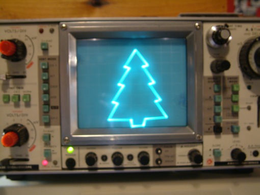
Recently on the Workshop88 mailing list, there was a discussion of things that could be shown at the STEAM fair (STEAM stands for Science, Technology, Engineering, Art and Math) at Glen Ellyn Public Library March 8. Jim Williams said an oscilloscope is a good thing to generate interest. I added the link to the oscilloscope vector Christmas tree that made the rounds two years ago. That was such an intriguing hack that I built it immediately. It requires only four parts besides the Arduino and the scope. Arduino does not have Digital-Analog Conversion hardware but the mega328 chip can do Pulse Width Modulation and johngineer uses that capability, integrating the pulse train in an RC network for his Christmas tree. Here’s the tree on my ancient Kikusui 5630:
Many people commented in johngineers blog and offered other vector images.
The possibility of an analog scope demo at the library set me to searching the internet for other interesting vector applications. I found this Youtube video encouraging, and there are a number of vector clocks out there. Then I found a page from hudson at the NYC Resistor makerspace site discussing vector generation on the AVR chips. That post mentioned the Hershey simplex fonts, with a link to a discussion and code. That implementation appears to be very old as the ^ (circumflex) symbol renders as an up arrow and that change was made to the ASCII character set in the sixties. It’s a proportional font and there is a column for the character width.
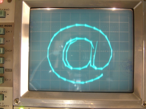
I decided to try implementing the Hershey font using johngineers simple RC integrating network. After some manipulation and scaling the font table I was able to display single characters entered from the serial port of the Arduino:
This is the absolute worst case glyph, uses all 56 vector pairs. One problem with vector fonts is the more vertices, the longer it takes to render the character. A problem that is exacerbated by the RC integrating network.
Some of the Hershey characters have skips indicated by a -1,-1 XY value pair. For example, the equal sign is rendered as two disconnected lines. A skip indicates that the vector trace needs to be turned off while moving to the next point. Fortunately my old oscilloscope has a Z axis input and by using a third Arduino digital pin, I was able to easily implement blanking.
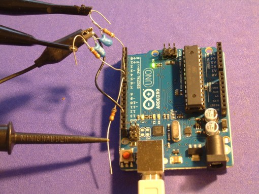
Here’s a picture of the Arduino showing the two integrating networks. The black wire goes to ground. My scope’s Z axis is connected through a third 10k resistor.
I found the Arduino quickly runs out of memory when you’re dealing with a 95 x 112 array so I had to learn how to force data into the flash program space using the PROGMEM keyword. I found an example that did almost exactly what I needed to do.
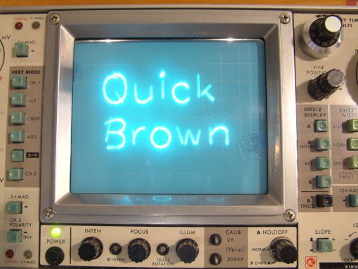
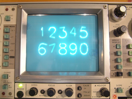
I’m old enough to remember Don Lancaster’s TV Typewriter. I thought it would be an even more interesting display if I could get multiple characters on the scope. So much programming and debugging later I have that working. I only made a 2×5 display as it’s just too slow. Filling all ten vector characters with the worst case @ sign takes close to a second to write the screen, but normal text is easily readable. Here is a group of letters:
and here is the number display:
Displaying multiple characters also requires blanking the trace between glyphs.
The Serial debug console that comes with the Arduino IDE can be used to enter text but a character-at-a-time terminal program works better. I use Minicom.
Note the rounded parts are much brighter than straight lines. This again is because there are more closely spaced segments and therefore the curves are painted more slowly. Also note some characters are distorted, like the seven above. I think this is because he RC integrating network continues to integrate the previous move while the next move is being generated. The first character position in each line is particularly subject to this distortion because the beam has to move a large distance from the last character.
The NYC Resistor page implementation does not use Arduino PWM, he uses an R-2R ladder DAC. This would be a great improvement from my simple RC network as all the delays in the sketch needed to wait for the RC network could be removed.
Any chance you would share your code? I have a bunch of students wanting to put text on an old XY display. Greg Kovacs, Stanford University
Look here.
This is very cool. Thank you for sharing. I immediately started wondering about porting my scrolling LED message sign to a scope, but then I realized as letters are clipped off the edges, there’d have to be more math to handle that and my brain doesn’t like math.
It will probably work if you just let it scroll off the edge. The scope won’t show the out of range voltage traces.
If you draw to a corner that is way off the line, does it try to plot that until it hits the edge? I seem to recall Atari used a trick to blast the edge of the screen to make it flash or something.
I think it will just run off the scope display. Keeping in mind there is a hard limit to how high or low the ADC voltage can go, you adjust the scope centering and gain controls to put the portion you want on the display. Note this is for an analog scope, I have no access to a digital version but believe the same principle applies.