More Fun With Direct Digital Synthesis: 32u4 and Fast PWM
32u4 Port
My 2015 winter project will be an expanded version of the Morse Code keyer I built last year. I now have a PJRC Teensy 2.0 controller board (from Sparkfun) to use. The Atmel 32u4 based Teensy 2.0 is even smaller than the Pro Minis I have been using. It is attractive because it has USB built in for program loading and serial transmission. And there’s lots of I/O pins available which will make an LCD easy to connect. I note that everybody making a 32u4 “Arduino” is defining a different pinout from the chip. The Adafruit Feather is quite ambitious, has it’s own IDE addon and can be bought with Bluetooth or WiFi included.
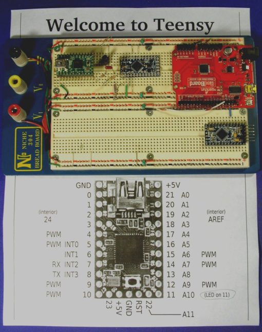
This breadboard photo shows the Teensy 2.0 at top left, Sparkfun Pro Mini at center, Sparkfun RedBoard top right, and a MicroCenter Pro Mini clone at bottom right.
PJRC has ported many of the standard Arduino libraries to their 32u4 Teensy form factor and these are included in your Arduino IDE when you download and install the Teensyduino addon. But my keyer sketch uses Direct Digital Synthesis to form a nice sine wave side tone which requires direct setup of a Pulse Width Modulation timer inside the AVR chip. My implementation is based on code from Jeff Whitlatch, KO7M. I used timer 2 in last winters UNO based keyer as that’s the timer that does tone() in the Arduino UNO and I completely superseded that function. Reading the data sheet on 32u4 shows that it doesn’t even *have* a timer 2. It has timer 0 (8 bit), timers 1 and 3 (16 bit), and timer 4 (10 bit). Digging into the Teensy Arduino libraries shows that PJRC is using timer 3 for tone() so I needed a port that just changed the timer used. Comparing the 32u4 data sheet with the Mega328 data sheet showed that the only difference besides the timer number would be in the Waveform Generation Mode bits. 32u4 has four WGM bits, Mega328 has 3. I used a mode setting that turns the 16 bit 32u4 timer 3 into an 8 bit timer and Success! The port was working in my test program.
Fast PWM
Phase Correct PWM in an AVR processor uses the timer in a manner that has it count from 0 to 255 then count back down to zero for each interrupt cycle. The PWM signal goes high on the way up and low on the way down. For an 8 bit counter, that’s 510 counts per cycle (read the data sheet to find out why it skips two) so with no clock scaling the sample rate is 16 MHz/510 or 31.4 KHz. In Fast PWM mode the timer counts from 0 to 255 then rolls over back to zero. A PWM wave on the output pin goes high on the way up and low on overflow. This results in some jitter on the PWM pulses but the sample rate is twice as fast, 16 MHz/256 or 62.5 KHz. I decided to try Fast PWM in the test program. It required only a change in the math that calculates the sample rate, and a slightly different set of WGM bits.
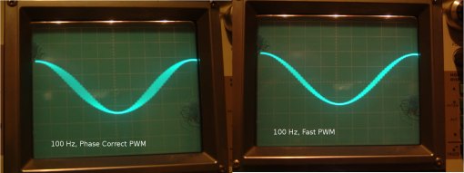
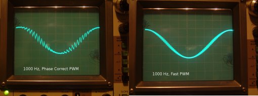
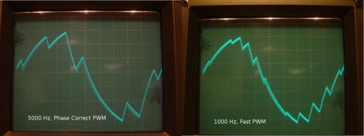
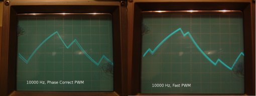
The following images show comparisons of the 31.4 KHz (Phase Correct) and the 62.5 KHz (Fast) rate tone waveforms from the test program. The PWM signal is filtered by a single 10k resistor and a 0.01 ufd capacitor to ground at the scope connection.
There is a clear improvement at the higher sample rate in the amount of “fuzz” on the waveform. The fuzz is at the sample rate and is the result of the 0.01 ufd capacitor integrating the PWM square wave. At twice the rate, the capacitor has half the time to charge or discharge. You can see at 5 KHz, the Fast PWM signal is much closer to a sine wave than Phase Correct. At 10 KHz, both are falling apart. A better output filter that cuts off the sample frequency would help but for morse keyer side tone from a tiny speaker, the average amateur radio operators ear won’t know the difference. I may try a switched capacitor filter some time in the future just to see. Watch this space.
Revision History
2015/12/08 The photos above are all from the 32u4 port. The program uses quarter wave symmetry to reduce the table size by a factor of 4. Two sketches, one running on UNO or other Mega328 controllers, the other for the PJRC 32u4 Teensy are at:
https://dl.dropboxusercontent.com/u/40929640/ArduinoSineSynth/Quarter_Wave_Demos.zip
I also back ported the changes to an earlier sketch that did not take advantage of symmetry. Scope traces were identical to the 32u4 port. Since the complete 360 degree cycle is specified, the code may be modified to generate arbitrary non-sinusoidal waveforms by manipulating the tables. Download at:
https://dl.dropboxusercontent.com/u/40929640/ArduinoSineSynth/Full_Table_Demos.zip
Each of these zip archives has a copy of the spreadsheet I used to construct the sine tables.
I want to salute you teensy2.0 Change duty cycles to adjust LED brightness, 5.10, …, 95% duty cycles, using PWM port. What I have to do ?
Just use analogWrite(number) where number is between zero (off) and 255 (full on). There is an example in the Arduino reference section https://www.arduino.cc/en/Reference/AnalogWrite