Archive for April, 2012

CAN Polling network

I added a variable to Kevin Smith’s library, the remote frame bit requests a response from other nodes on the buss.  With this I was able to implement a polling scheme. The master requests a data update every 10 seconds and only then will the remote transmit routine readings.  This cuts down chatter on the buss.  I also partitioned the 11 bit id field into a 5 bit node identifier and a six bit data type indicator.  Each remote station will be assigned a unique identifier, in this photo, the remote is number 31.

Remotes can still broadcast autonomously, for instance a notification that a door is opened will be sent immediately to all master nodes.

Wish I knew more about C++ to deal with these libraries.

CAN Polling network

Master polling the remote for data

More Adventures with CAN

I’ve now etched and assembled three of the CAN transceiver modules, two with shield headers and one without as a breakout.  I probably should have made them all breakouts because you can’t easily get at the Arduino pins when the transceiver is plugged in.  I had to epoxy the headers to the transceiver board because on the single sided board there isn’t enough copper for good physical support.  Also discovered the bearings in my Dremel tool are going bad. In the good news department, my Cupric Chloride bath worked OK on the second batch of boards after about five hours of air bubbling to regenerate after I dumped in two feet of number six wire to get the Cupric  concentration up.  I’m not a chemist, I don’t know what I’m doing, but it works.

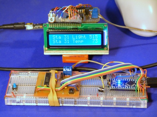
Two Arduinos are now wired together in a CAN network. One is reading a photocell, also an LM34 temperature sensor and it’s transmitting those measurements every second to the other node.  At the destination, temperature and light readings are shown on a 16×2 Liquid Crystal display. The software is based on one of FazJaxton’s examples.

There is 100 feet of CAT5 cable between the two transceivers in the photo. Only the blue pair is connected, CAN doesn’t need a ground.  In a home monitoring network, CAT5 is a logical choice as it is easy to find. and the other pairs could be used to feed power to the remote sensor nodes.  Don’t know if CAN will coexist with 100bT Ethernet, will have to try that some time.  Another possibility is standard telephone wire (IW) but would have to find the twisted kind.  Most telephone wiring is two pair and only one pair is used.  So if the stars are aligned correctly, you could use the other pair in your existing phone jacks for CAN.

Two node CAN network

It’s a bit of a pain to develop two Arduino nodes at the same time as the USB serial ports keep moving around every time you unplug a cable which confuses the IDE.

Maybe tomorrow a third node.

Printed Circuit Boards by Toner Transfer

I took a short class in PCB techniques at Workshop 88 last summer and since then have been accumulating the necessary kit to make my own boards.  Jim Williams taught the class and he uses a Hydrochloric Acid/Hydrogen Peroxide mixture to etch the copper.  These evil sounding chemicals available at most hardware stores are actually more benign than the Ferric Chloride or Ammonium Persulfate  from Frys. The Peroxide acts as an oxidizer and is used up pretty quickly leaving the HCl and copper chloride.  You can bubble air through the mixture, which converts the copper chloride into cuprous chloride which by itself is a good etchant.  So the brew is more or less renewable.

I decided to try the laser printer Toner Transfer method for my first project, a modified Arduino shield that supports an MCP2515/MCP2551 chip set for a CAN buss network.  My version is a riff on work done by Kevin Smith. His web site provided an Eagle schematic and board as well as example software and libraries to use the 2515. I modified the Eagle files, removed some parts and printed the result two up with my Lexmark 4039 10+ laser printer.  The Lexmark can be set to print an extra dark image.  This is the result:

PC board progress

Top right is one half of the two up printout from Eagle.  Top left is one of the patterns ironed onto a piece of single sided PC board material, the bottom right image is a board  fresh from etching and drilling, bottom left is an assembled board mounted shield style on an Arduino clone.

There are many sites on the net where you can research the toner transfer method.  My technique is to crank the print density on the 4039 to up to “dark”, then print on paper salvaged from a slick magazine.  The classified pages from a “Fine Woodworking” worked well.  I put the printout image side up on a table, then carefully place the precut single sided PC blank on top of the image. Then fold the paper up over the edges of the board.  Now put the blank foil side up on a piece of plywood that forms my ironing board, place the printout over the blank using the fold lines as a guide. Iron at high heat for about two minutes.  Remove the Iron and roll the paper firmly with a brayer while it’s cooling.

The printout is now melted onto the board copper.  trim the paper leaving about a quarter inch all around, then soak in warm soapy water for a few minutes.  The top layer of printout paper will peel right off, then gently rub the surface with fingers. The remaining paper will slough off.  Finally a very gentle scrub with a soft toothbrush to make sure the paper residue is cleaned out of the pad holes.

WB8NBS

NBS
This Blog will document projects I have
in progress or completed. You can search for my
handle on Flickr, Facebook, YouTube, or Picasa
for photos. I will link some of those here.