Frame and Panel Construction – Part 2: The Frame
These two WordPress pages document my method of constructing a frame and raised panel door. I need to make a pair of these about 30″ x 18″ to replace an ugly entrance to the crawl space in my home. Each door will be a single solid Pine panel, the frame will be about 2 inches wide with an Ovolo molding on the inside edge. An Ovolo is a quarter round with a small step. It creates a shadow line around the inside of the frame which softens the edge visually.

Completed practice panel
Another goal is to, as much as possible, use only hand tools in the project. A few years ago I acquired a small panel raising plane at an estate sale and it’s time to put it to work. This photo shows some of the tools used in creating a frame.

Hand tools used in frame construction
Three episodes of “The Woodwright’s Shop” contributed to my techniques.
“Raising Panel-Zona” describes several methods of making a raised panel.
“Painless Panel Doors” where Roy constructs a mortise and tenon frame.
“Simple Sash Restoration” shows how to join a frame with molding around the inside.
To understand and practice the procedure I’ve made several small framed raised panels. These will find their way into a box or maybe a lamp sometime in the future. This procedure builds a frame to house a pre-constructed panel though usually the frame will be built first, made to fit an existing opening, then a panel constructed to fit.
This, the second page of my frame and panel series describes the frame construction. It turns out that making the frame, with a molded inside edge, is harder than building the raised panel.
My practice raised panels were cut from 1×8 pine, resulting in a 7 1/4″ square panel. The frame begins with two 10 3/4″ rails and two 11″ stiles cut from a pine 1×4 ripped down the middle.The stiles are longer than needed to make them more likely to survive the mortise chisel.
The raised panels have a centerline mark so the first step is to mark a centerline as an alignment reference on the frame pieces.

Center line used as reference
The stiles and rails are inspected. the best sides marked as face, and a position in the frame picked and marked.

Two stiles, two rails with face sides marked
The panel with grain vertical, and both rails are turned bottom up and aligned with the center marks. Four tenon shoulders must be located on the rails. These are aligned with the inside edge of the panel back rabbit but an allowance should be made for the panel expanding across the grain in humid conditions. I use a thick steel ruler as a spacer which results in about 1/32 inch extra. The 12 inch ruler is flexible and bent down so it butts up tight against the rabbit. Both left and right side tenon shoulders are marked on the rails. They are knifed later.

Marking for rail shoulders
On the face side, the tenon shoulder is a quarter inch farther out to allow for coping the molded edge. Here the back side line has been extended up the rails side and I used a 1/4″ brass spacer to locate the face side shoulder.

Quarter inch spacer defining face shoulder
This shows the offset shoulder laid out. The face and rear shoulder lines will be knifed to help with accurate sawing, the short side lines are not knifed.

Rail tenon offset to allow coping
My practice raised panels varied a bit in depth so here I am checking the distance between panel top surface and the bottom of the rear rabbit. Ideally the distance between the top surface of the panel and the bottom of the rear rabbit groove will be 9/16″ which will allow 1/4″ panel raise, 1/4″ panel edge thickness, and 1/16″ for the Ovolo molding.

Measure for tenon depth
Set the mortise gauge outside pin to exactly the depth measured above. The separation between the two pins is set to exactly the width of my quarter inch mortise chisel.

Set bottom pin of tenon gauge
Tenons are marked with the mortise gauge then penciled in lightly. Note here the face side line is scratched shorter that the rear side because of the offset shoulder.

Tenons outlined with pencil
Now to cut the tenon cheeks. As Roy shows, part from one side, part from the other, then clamp the rail vertical and saw down to the shoulder line.

Sawing tenon shoulders
Before the tenon shoulders are cut free, a groove to receive the panel is cut with a plow plane. The depth stop is set for 5/16″ a little deeper than the panel rabbit, we don’t want it to bottom out. he plane fence is carefully adjusted so the groove runs right down the center of the tenon.

Plowing the rail groove
Once the groove is done it’s checked for depth with vernier calipers. A dry fit of the raised panel confirms the groove.

Panel dry fit in freshly cut groove
Next the tenon shoulders are cut off. A bench hook supports the rail while sawing.

Removing tenon shoulders
The frame groove defines the inside extent of the tenon but the outside is marked 3/8″ in from the edge. The cut will not go all the way to the offset tenon shoulder, it stops about 1/8 inch from the shoulder to create a haunch. The haunch fills excess space in the stile groove and it will be trimmed later to fit exactly.

Gauge outside tenon edge
I’m using a fine tooth dovetail saw to cut the outside of the tenon. It is important that the inside and outside edges be parallel but precise width is not critical. Saw in at the haunch then cut vertically on the line.

Sawing outside tenon edge
With the outside wood removed, these start to look like real tenons. In this photo you can see the offset top shoulder and the short haunch left.

Sawn tenons with haunch stub
Nobody’s perfect and my tenon sawing technique needs a lot more practice. In the meantime I made a jig so I could true up the sawn surfaces with a router plane. I cleaned each face until the tenons measured exactly 1/4″ with my calipers. This also ensures that all four tenons are the same depth from the rail faces. The jig is just two pieces of 3/4″ MDF clamped to the table top with a machine screw. They support the router plane while it’s doing it’s thing.

Tuning tenons
Now the completed tenon outlines have to be transferred to the rails to define the matching mortises. I dry fit the grooved rails to the panel and lay that assembly on the rails. Everything is rear side up in this photo and the rails are aligned with the panel using the center line marks.

Dry fit to locate mortises
The tenons lay flat on the blank rails making it easy to mark where the mortise edges will go.

Transferring tenon edges to rail
Here you can see both tenon edges are traced on to the rails.

Tenon edges traced onto rails
I use an engineering square to bring the marked mortise edge lines around to the sides of the stiles. Then the mortise gauge defines the sides.

Gaugeing mortise sides
Pencil in the gauge lines and the stiles are ready for the mortise chisel.

Marked mortise locations
My mortise chopping technique is straight from Roy’s video. Chop from the far end to near going deeper with each eighth inch increment, reverse the chisel and chop back near end to far. Straighten the edges and in this soft pine you will be half way through. Turn the stile over and repeat, chopping all the way through.
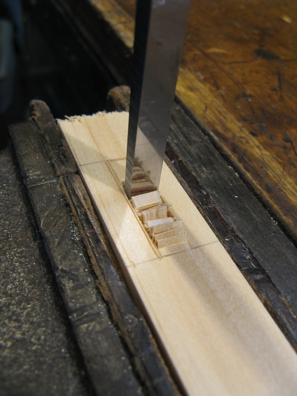
Chopping one side of a mortise
I
I use an engineers square to check for true inside edges. Trim with the mortise chisel if not.

Checking straightness of mortise edges
Once the mortises are cut and dry fit successfully, I plow a groove in the stile. If all measurements were good, the groove will go through the center of both mortises.

Plowing a groove in a stile
This is a face side dry fit of all four joints. It’s looking like a real frame now. If the tenon shoulders were carefully cut, it will be square.

Dry fit to check squareness
Molding the inside edges starts with cutting a thin rabbit on the inside edge. I use a Miller Falls 85 for this with the fence set to a quarter inch width and the depth stop is set to 1/16″. This should leave a quarter inch square shoulder on the inside which will be rounded over.

Planing board set up to rebate
It took about a dozen strokes with the rabbit plane to make the 1/16 inch step.

Rabbit plane defining Ovolo
In this photo you can see the shadow line created by the small rabbit.

Small rebate defines Ovolo
To begin the Ovolo round over, I chamfer the edge with a block plane. This makes it easier for the molding plane as much of the wood is already removed. It’s a woodworking principle to always use the tool with an easily sharpened blade first.

Roughing in the Ovolo shape
I have this small hollow plane, it has a 5/16 cutter. The round edge is smaller so it takes some fussing and finally a few swipes with sandpaper to get the curve correct.

Hollow plane smoothing Ovolo molding
When all four pieces are molded, the frame is dry fitted and the edge of the rails Ovolo step carefully transferred to the stile. I also transfer the outside edge of the rail to the stile but since the end (horn) of the stile will ultimately be cut off, that’s not really necessary. The molded edge between the two marks is removed.

Marking stile molding for removal
I carefully chisel out the molding of the stile between the marks. The rail’s longer tenon shoulder will fit into this recess.

Removing stile molding
The next step is to cope the rounded molding on the rail. It will fit over the stile molding and give the illusion of a 45 degree miter. This procedure is right out of “Simple Sash Restoration” and begins by using a template to precisely miter the corner of the rail molding.

Trimming rail molding with miter template
A close up of the mitered rail molding.

Mitered rail molding
Now the mitered bit is coped. a small scribing gouge is used to remove the wood visible when you look straight down at the miter. This gouge is a little too big for this job but it’s all I have.

Coping the rail molding
This photo shows the coped corner.

Close up of coped Ovolo
The coped joint is dry fit and trimmed to fit closely. Trimming might require fine tuning the cope, planing one of the tenon shoulders, and trimming the haunch. Sometimes it helps to undercut the shoulders a bit. If the shoulders were planed, check the assembly for square afterwards.

Dry fit coped Ovolo
Success is a dry fit of all four joints with no gaps.

Dry fit all four pieces
With the panel inserted you can see what the final product will look like. Since the whole reason for separate frame and panel construction is to allow the panel to move a bit, the panel must be finished before the assembly is glued up. Finishing the glued up frame would be easier but would risk an unfinished line appearing at the panel’s long grain edges in dry weather.

Panel inserted – front
The back side doesn’t show anyway but the rear of the assembled frame and panel should be flat if everything was done correctly. The protruding horns on the stiles and tenon stubs will be sawn off and planed smooth after the final glue up.

Panel inserted – rear


