Arduino – Si5351 Powered Signal Generator
Device Description
For a long time I wanted a general purpose signal generator. Now Direct Digital Synthesizer hardware is available on a single programmable chip. The Analog Devices AD9851 is used in many ham radio projects, also widely used is the Silicon Labs Si5351. Either of these can be obtained from many sources such as Adafruit, Sparkfun, or on EBay and there’s lots of information on the internet. Even Amazon has them. A few dollars gets a DDS chip that will tune continuously from audio to VHF mounted on a small breakout board. I purchased an Si5351 board from Etherkit because they offer a version with a TCXO.
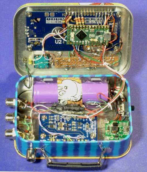
Silicon Labs makes the Si5351 in several variations. It’s intended use is as a multiple output clock generator with up to eight individually programmed frequencies. Most commonly available breakout boards though, use the A version with three outputs. Digikey has the bare chips for less than $1. Connectors are optional, most boards are set up for SMA female jacks. The signal generator I built brings out all three outputs but I used good old RCA phono jacks. SMA connectors are wonderful but the cables to use them are pricey. My box will be used to check and align receivers so precision impedance control is less important.
AD9851 chips have a real Digital/Analog converter on board, it uses an amplitude lookup table to produce a fair sine wave. The data sheet says:
“The AD9851 uses an innovative and proprietary angle rotation algorithm that mathematically converts the 14-bit truncated value of the 32-bit phase accumulator to the 10-bit quantized amplitude that is passed to the DAC. This unique algorithm uses a much-reduced ROM look-up table and DSP to perform this function.”
- expand to controlling all three outputs
- setting up frequencies using rotary encoder and LCD menus
- save and restore setup in EEPROM
- add output power change to the menus
- add output OFF to the power menu
- add sweep capability with menu control
The Box
A thin metal gift card box was cut up to form an enclosure for the generator. It is about a quarter inch larger than the usual Altoids tin in all three dimensions. I needed the extra volume to fit in a battery and charger removed from a cheap phone power pack. These booster packs usually contain a single 18650 cell and it just fits.
Operation
On power up the unit reads saved frequency settings from EEPROM. The display then shows frequency, current port selected, and the output power setting.
Click one of the three buttons to change the port selected to display on the LCD.
Rotating the encoder knob will change the frequency digit under the flashing cursor. Press click the encoder knob to change the digit under the cursor, you can set the cursor to change digits from 1 Hz to 10 MHz.
Hold one of the port select buttons down and turn the encoder knob to change output power for that port. The chip has choices of 8 milliamps, 6 mA, 4 mA, 2 mA, and OFF. Silicon Labs’ spec for driver impedance is 50-85 ohms.
If any of the above settings are changed, the software waits ten seconds, then copies the current settings into EEPROM. In the event the unit gets confused, it can be restored to last saved settings by cycling the power switch. Also it can be returned to default settings by holding down all three port select buttons, while powering up.
Sweep Function
Sweep is accessed from a separate menu. Press down the encoder knob for more than two seconds (a long press) and release to enter sweep parameters for the currently selected port. A short click of the encoder knob will advance the menu through the sweep choices, currently +/- 0, 1000, 5000, 15000, 50000, or 150000 Hz. The unit sweeps from frequency minus that amount to frequency plus that amount so the total width of sweep is twice the setting. Sweeping is done by reprogramming frequencies in 20 steps between the limits.
A second long press of the encoder knob will return to the frequency menu. The letters “sw” appear on the LCD to indicate that that port is set up to sweep. All three ports can be set up but only the port currently selected in the display will be sweeping at any given time.
A pulse is available at a phono jack on top of the box to trigger an oscilloscope at start of each sweep iteration.
Sweep parameters are not currently saved in EEPROM.
The Software
Addendum April 4, 2018: Amplitude Modulation Experiment
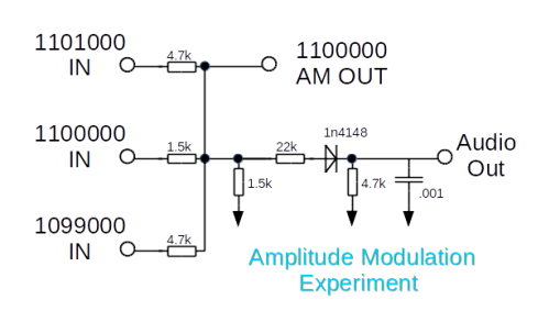
The Si5351 was set to equal drive power on all three outputs. I examined the output on the oscilloscope, channel 1 connected to AM Out, channel 2 to Audio Out with sync taken from Channel 2. The result is not encouraging. It does output an amplitude modulated signal but the waveforms are bizarre. I see a blocky square wave changing at a 1000 Hz rate but there is some phase problem I can’t control. This is the best I could capture:
Connecting an audio amp and speaker does show a 1 KHz tone if the phases happen to line up just right. I found that setting any one of the generators to be one Hz off frequency results in a rolling pattern with about a one per second beat note in the speaker.
This method of faking Amplitude Modulation is certainly not precise or controllable. Setting one of the outputs off frequency by a few Hz does give a useful warbling tone in an AM receiver.
Files
https://www.dropbox.com/s/hk7nc063ipjisr7/SignalGenV1.11.zip?dl=0


Nice work! Looks like you used a Teensy 3.6 with 3v3 I/O. Presume the 2k2 resistors are for level shifting.
I am thinking of bringibg out the 3 clocks on my next si5351 transceiver so that it can double as a sig gen for future projects. But a dedicated MCU and si5351 is a better idea.
Like your mix of radio homebrew and fine woodwork!
It’s a Teensy LC I had on hand. Yes the 2.2k are for level shifting, I read somewhere on the PJRC site that would adjust the levels. I think it would be possible to declare the LCD without the R/W pin and it would never try to write on the data pins but I wanted to be conservative. Inhave a Teensy 3.5 and a 3.6 but havn’t done anything with them yet. Next project is a PID temp controller for a toaster oven. will use it for tempering tool steel and maybe soldering.
Yes the Teensys are cracking MCUs, I have a 3.6 but havent fired it up yet. I’ll watch your projects with interest.
Really enjoyed this article, is there any way I can receive an update sent in an email when you publish a fresh article?
There is an RSS feed option near the bottom of the right hand column.
I used an UNO & 1602a v2 LCD and works great, only had to change to A1 from A6 for the encoder switch. Great article. May I post on other sites with a few updates, will keep your name in sketch.
Sure. Send me pictures and I will attach to my page.