Archive for the ‘ Uncategorized ’ Category

Sand Clock – 2024 (this post is in progress)

Genesis

In mid-2023 my Brother in Law asked me what I would like for my birthday. After some back and forth I sent a list of Adafruit parts with which I could construct a second digital clock based on the design and software from my initial effort in 2022 (see “A Clock With Benefits“). The Adafruit parts would be slightly cheaper. I offered to gift him the clock for his 2024 birthday.
Adafruit Matrix Portal S3 #5778
Adafruit 64×64 RGB Matrix Panel #5362
Adafruit 5V, 4A Power Supply #1466
Adafruit DS1307 Real Time Clock #3296
The project required other small parts most of which I had on hand. Adafruit was out of stock on these major parts so did not have everything until November – which was a bad month for me due to medical issues. So the port started in December 23. I had a nice piece of beautiful 1″ Padauk which was resawn and milled into 5 1/4″ x 2 1/2″ x 3/8″ pieces to make a case for the new clock. A bit of salvaged plywood made the back panel and the front panel is smoked plastic diffuser (Adafruit #4749)

Clock Case Material
Clock Case Material

My circa 2022 clock used a PJRC Teensy 3.6 with a Smart Matrix shield from Pixelmatix. I thought software written for the Teensy would easily port over to the Adafruit Matrix Portal. I was wrong. The biggest problem was that Smart Matrix libraries used a three byte 8bit-8bit-8bit RGB method to represent colors. Adafruit’s libraries use a 5bit-6bit-5bit RGB scheme all packed into a sixteen bit integer variable. Also Adafruit has no method for globally changing the brightness of the display. Smart Matrix makes that easy but for the S3, I had to write my own procedure for adjusting brightness as the clock running full song was annoyingly bright in a dimly lit room. I will outline my method later in this post as it may be useful to someone else.

In 2022, the Teensy 3.6 had a Real Time Clock built in but no acceleration sensor. I used an Adafruit LIS3DH sensor glued to the back cover. The Matrix Portal board in this years version has a built in acceleration sensor but no Real Time Clock. I used an Adafruit DS1307 clock. It is mounted directly under the Matrix Portal board.

Breadboard Mockup
Breadboard Mockup

I am not using any of the wireless capability of the Espressif ESP32 processor on the Matrix Portal S3 board. That’s above my knowledge level at this time. The S3 chip proved to be surprisingly brittle and the Arduino IDE produced code crashes a lot. Simple things like adding a delay() or Serial.print() to the sketch would sometimes cause the software to crash all the way back to the boot loader. Debugging was difficult under these conditions and I would not recommend using the Adafruit Matrix Portal S3 under Arduino IDE until Espressif does something about this. I am running ESP32 library 2.0.15 and Arduino IDE 2.3.2. Note: Espressif is showing a scheduled update to version 3.0 in April 24.

2024 Clock Operation

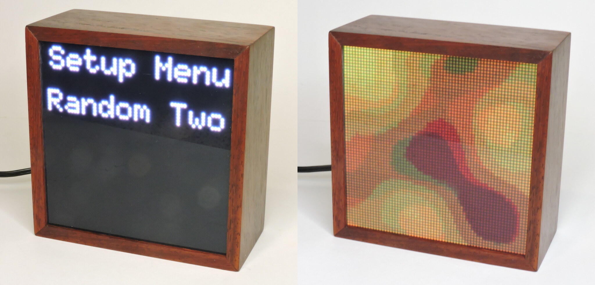
Here are all the screens available on this version. Some have changed from the 2021 code and some have been added. There are now sixteen options in the setup menu. To enter Setup Menu mode, press and hold the Function button for three seconds (a long press). You can then scroll through the screen options using the Up or Down buttons. When the desired screen is listed, a half second press on Function (a short press) will select and start that mode. Two of the screens, Brightness and Clock Set have settings that are manipulated using the Up or Down buttons.

This is the basic clock display that started the whole project. A straight forward digital 12 hour display. It also has the Sand Nature, when activated by shaking the clock three times in two seconds the display will turn into digital sand which can be poured around the screen by tilting the clock. Sand is displayed for 30 seconds then fades back to the clock. Pressing the Down button will return a sand display to the clock screen immediately.

Digital Clock
Digital Clock

The software can also generate a slow soothing background for the Digital display. Two different backgrounds are selectable, Random One is more bluish, Random Two has warmer colors. These screens do NOT have the Sand Nature.

Analog Clock - Type 1 Background
Digital Clock – Type 1 Background
Digital Clock - Type 2 Background
Digital Clock – Type 2 Background

An Analog Clock is also available for those who prefer Retro time keeping. The bare Analog Clock also has the Sand Nature when shaken, which can be cancelled by pressing the Down button. It was based on code posted to Hackster.io in 2021.

Analog Clock
Analog Clock

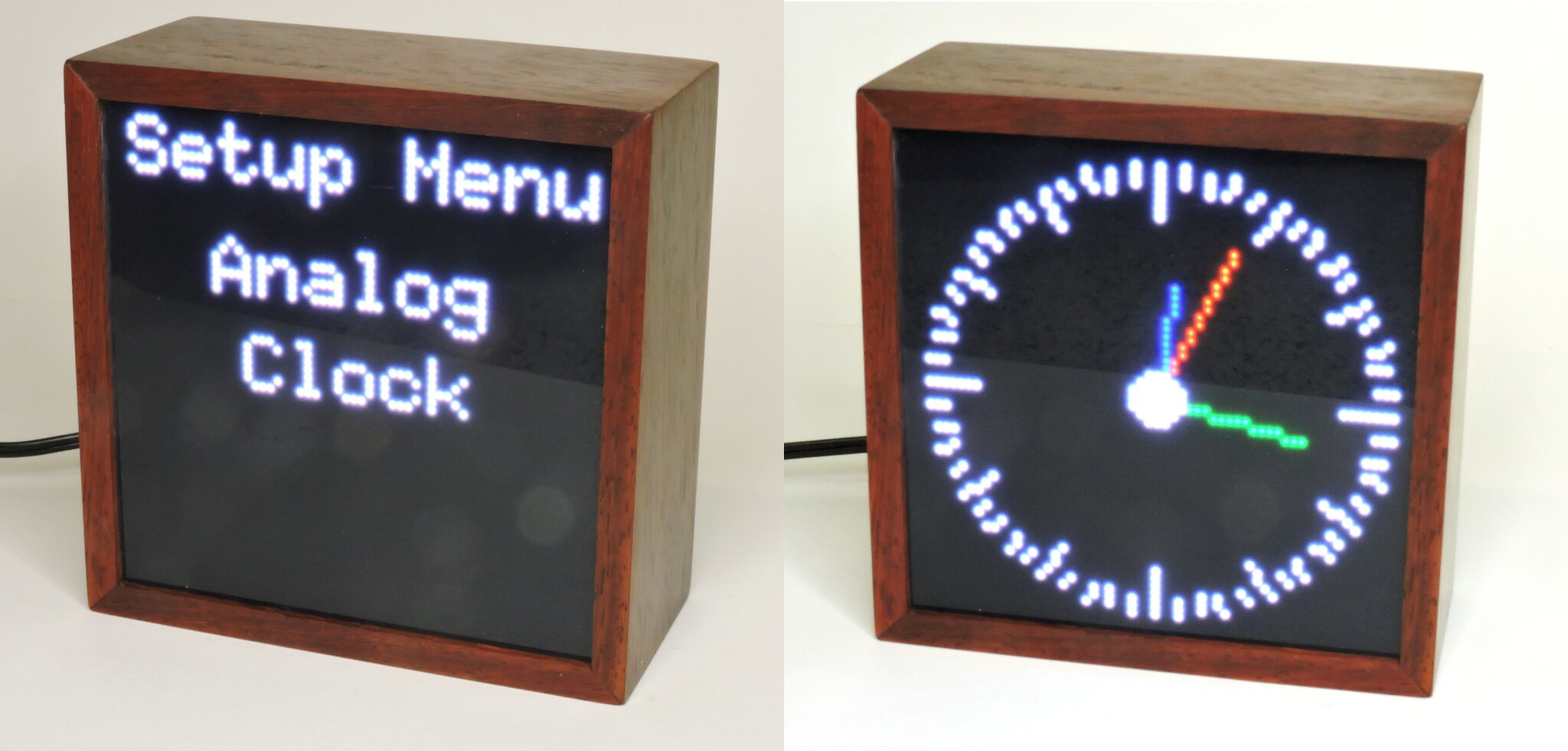
Similar to the Digital Clock, the Analog version has two colorful changing backgrounds available.

Analog Clock - type 1 Background
Analog Clock – type 1 Background
Analog Clock - type 2 Background
Analog Clock – type 2 Background

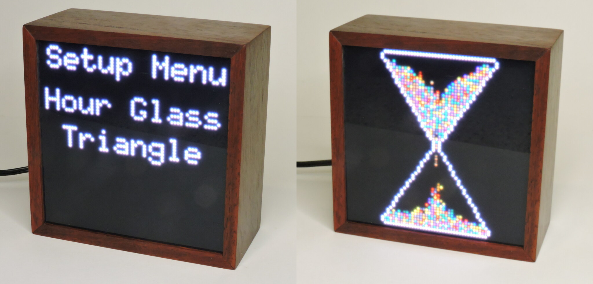
Next, for those who REALLY need Retro time keeping there are two hourglass screens. They differ in the shape of the simulated container. Triangle Hourglass empties in about 50 seconds, the rounded version in about 90 seconds. These can be reset by a press on the Down button.

Hour Glass - Triangle Version
Hour Glass – Triangle Version
Hour Glass - Rounded Version
Hour Glass – Rounded Version

If you just want something soothing, two screens are available showing only the slow changing color display used in the clock backgrounds. These backgrounds are adapted from the Noise demo sketch included with the FastLED library.

Random Colors - type 1
Random Colors – type 1
Random Colors - type 2
Random Colors – type 2

The next menu item is a Magic Eight Ball simulation. If you are of a certain age you may have had one of these to help make life’s decisions. It is a billiard 8 ball filled with thick fluid. There is a window and multi sided dice floating inside which allow a random phrase to appear in the window. This toy is still made and sold by Mattel.

A random response is triggered when the clock is shaken. A hand full of digital sand is thrown in just to make the display more interesting. Pressing Down will reset the display.

Magic Eight Ball
Magic Eight Ball

The clock has two slightly different implementations of John Conway’s Game of Life, beautifully coded by Jason Coon. If you are not familiar with Conway’s Game, I highly recommend reading the fascinating Wikipedia article. Conway simulates cellular growth through multiple generations (think bacteria on a Petri Dish). There are only four rules:

  • 1. Any live cell with fewer than two live neighbours dies, as if caused by loneliness.
  • 2. Any live cell with two or three live neighbours lives on to the next generation.
  • 3. Any live cell with more than three live neighbours dies, as if by overpopulation.
  • 4. Any dead cell with exactly three live neighbours becomes a live cell, as if by reproduction.

A game runs for one minute then automatically resets. Pressing the Down button will reset the display immediately. Pressing the Up button will buy another 30 seconds of run time in case something interesting is going on. The two selectable versions differ only in the Blur option. If Blur is selected, Every other run has the display blurred a bit.

Conway's Game of Life
Conway’s Game of Life

The last variation is Sand Toy. It just puts up some digital sand to play with. There is an Adafruit logo planted in the middle that has blocking set so the sand will not run over the logo. Sand Toy will reset if the Down button is pressed.

Adafruit Sand Toy
Adafruit Sand Toy

Brightness and Setting the Clock

These final two setup options bring a user to a second screen with settings options.

Selecting Brightness setup takes you to another screen which has the ability to change how bright the LED display is. Use the Up/Down buttons to change the value, you will see the effect in the colored squares surrounding the Brightness number. The range is 10 to 255 and to speed things up, the number changes in steps of ten. Short press the Function button to make the change permanent, then long press Function to exit the Brightness screen. Then you can move to any of the other clock menu items.

Adjust Display Brightness

Finally there is the Clock Setting option. Seven fields are changeable. Hour, Minute, Second, AM/PM, Month, Day, and Year. You move from field to field with a short press on the Function button after which the Up/Down buttons can be used to change the number. A long press on Function writes the settings into the clock chip and returns to the Setup Menu.

Clock Setting
Clock Time Setting

Software

All software was written via Arduino IDE, currently version2.3.0. The environment is C++ though it is cut down to vanilla C. Much of the Clock is based on demonstration programs which usually come with the libraries. Several Adafruit Arduinoish libraries are used though Adafruit puts most of it’s development effort these days into Python, which I have not yet embraced. Python was not as prevalent in 2022 when I made the first clock, and for this effort I wanted to reuse as much of that code as possible. The sketch is a mashup of code I wrote, code lifted from library examples, and code lifted from the Adafruit learn guides. Some of the modules were adapted to the Matrix Portal S3 with 64×64 LED panel separately as a debugging exercise. These sketches are in the Finished_Demos directory.

I promised to discuss my method for globally changing screen brightness. The method relies on the sketch using fixed tables of color which is the case for most of the Adafruit libraries. Tables sometimes are specified in an array of 565 colors like:

  • colors[0] = matrix.color565(64, 64, 64); // Dark Gray
  • colors[1] = matrix.color565(120, 79, 23); // Brown
  • colors[2] = matrix.color565(228, 3, 3); // Red
  • colors[3] = matrix.color565(255,140, 0); // Orange
  • colors[4] = matrix.color565(255,237, 0); // Yellow
  • colors[5] = matrix.color565( 0,128, 38); // Green
  • colors[6] = matrix.color565( 0, 77,255); // Blue
  • colors[7] = matrix.color565(117, 7,135); // Purple

or separately like this:

  • #define BLUE 0x001F
  • #define RED 0xF800
  • #define GREEN 0x07E0
  • #define CYAN 0x07FF
  • #define MAGENTA 0xF81F
  • #define YELLOW 0xFFE0
  • #define WHITE 0xFFFF

These end up as 16 bit unsigned integer variables with the Red, Green, Blue numbers packed as five bits Red, six bits Green, and five bits Blue sometimes typed as color565. You can’t just multiply one of these by a fraction, you have to multiply each component color separately.

My approach was to specify a fixed set of reference colors as three byte RGB equivalents in a header file (rgbColors.h). The Brightness function then on request multiplies those RGB values by a desired fraction and converts the scaled 8,8,8 result into a 5,6,5 sixteen bit working table inside the sketch. Any sketch process using color tables will access the internal working version which can be changed at any time by invoking the Brightness function. ESP32 does have a floating point processor so this method works quick enough to program a smooth fade out of the digital sand and fade in the clock screens.

Another issue I found early on is the ESP32 will not start if the program is expecting a serial port and it doesn’t find one. I set a tag variable at the beginning and checking for it’s existence, enable or disable all Serial functions. This allows debugging with Serial but commenting out the variable will let the ESP32 start up when the USB-C is not connected. Every instance of Serial.print must be wrapped with #ifdef serPort and #endif.
Variable setup:
// Matrix Portal will not start if it’s looking for serial port so
#define serPort // Comment this line out if not using Serial.
Using the serPort tag later:
// Initialize LED matrix…
ProtomatterStatus status = matrix.begin();
#ifdef serPort
Serial.print(“Protomatter begin() status: “);
Serial.println((int)status);
#endif

Hardware Issues

There is the afore mentioned tendency to crash back to the bootloader. Unknown at this time if this is a hardware, firmware or software issue.

The ESP32 S3 requires a two button press sequence to put the chip into software upload mode. Then a button must be pressed to start the sketch. This is a PITA when have fat fingers and you’re debugging and uploading 10-15 versions per hour. It also means you have to open up the box to update the load as adding external pushbuttons and an external USB jack is a bad idea.

The Adafruit pushbutton switches I used for Up/Down/Function bounce horribly sometimes causing an intended selection to be skipped. I have a function to reliably read cheap pushbuttons but it depends on using analogRead on the button. I found analogReads on the ESP32 take 10 milliseconds which was limiting the clock frame rate to about 30 FPS. Switched to digitalRead and read time dropped to 6 microseconds, the frame rate increased to about 55, much more acceptable.

We bought the same part number 5362 64×64 LED matrix as I used in my 2022 Teensy version. The display looked way off and it turned out the LED panel was wired differently. See this post:
https://forums.adafruit.com/viewtopic.php?p=997072&hilit=5362#p997072
Apparently the HUB75 protocol does not specify which channels connect to which colors and many people have reported this issue especially with LED panel purchases direct from China. In my source code package, there is included in the “Finished_Demos” directory a program “Noise_Demo” which starts up with full screens of the six primary color choices, Red, Green, Blue, Cyan, Magenta, and Yellow. Running this sketch should immediately point out anomalous wiring in your panel. The fix is simple. Since assigning color output pins is part of the initial setup, just rearrange the assignments to correspond with your matrix panel. There are two sets of pins that must be changed:

// Matrix purchased in 2023 has red – blue switched
// PinOrder is upper-half red, green, blue, lower-half red, green blue
//uint8_t rgbPins[] = { 42, 41, 40, 38, 39, 37 }; // Original
uint8_t rgbPins[] = { 40, 41, 42, 37, 39, 38 }; // Red, Blue swapped

Source Code History

Sand Clock: Settings

I’m making a separate post here on the clock’s settings menus so as not to clutter up the first page. There are three buttons on the rear panel, Function, Up, and Down.

Rear View of the Clock

There may be a reset switch in the future because of a software bug.

The Up and Down buttons do exactly what they say. Function has two jobs depending on if it has been a short time pressed (less than 1.5 seconds) or a long press (greater than 1.5 seconds). Generally hold the F button down for a count of 3 to trigger a long press.

Short press is used to select something. Long press enters a menu item.

There are 12 menus. The current operating display is stored in flash memory so normally a power cycle or reset brings the clock back to the display that was running before the interruption. But selecting a different display through the menu may activate a bug in the software. The act of writing something to flash does something to the processor clock and causes the display to flicker. If this happens, the fix is to cycle power or reset the processor.

When you enter the Setup Menu mode with a long press the clock will go to the menu item associated with whatever display was running. Once in the Setup Menu mode, use the up or down buttons to move to the display you want.

Digital Clock

This menu selects the original digital clock which started this whole project. The digital display will melt into sand for 30 seconds if the clock is shaken 3 times in less than three seconds. Sand runs for 30 seconds after which it fades to black and the digital clock fades back in. If the clock is shaken during the fade to black period, you get another 30 seconds of sand. A short press of the Function will exit the menu and display the digital clock.

Digital Clock Settings Menu Item

Random One and Random Two

Two stand alone random color items are available just to get a mood display. These were extracted from FastLED_Functions, part of the SmartMatrix demo library. The two selections are very similar but Random Two has warmer colors. Short press Function to begin the display.

Select Random Color Screen

Random One and Random Two with Digital Clock

Selects the Random One or Two background display with the Digital Clock overlay on top. The colored background precludes doing the sand simulation. Short Press Function to engage the display.

Select Digital Clock with Random Color Background

Analog Clock

Selects the Analog clock display derived from a project found on the Arduino Project Hub. This is the bare clock but it has the melt into sand when shaken feature. As with the Digital Clock, the sand runs for 30 seconds but gets an extra life if you shake the clock while it’s fading out. Short press the Function button to select this display.

Bare Analog Clock

Random One and Random Two with Analog Clock

These menu items select the Random Color background screen with the Analog Clock on top. These can’t do the sand simulation. Short press Function to select one of these displays.

Select Analog Clock with Random Color Background

Hour Glass

This starts the Hour Glass display. Turn the clock upside down to continue the Hour Glass time. As programmed, it takes about one minute to empty top to bottom. Short press Function to select this display.

For Selecting the Digital Hour Glass

Magic Eight Ball

Selects the Magic 8 Ball function, best described by this Wikipedia article. There is a flowing sand display, but a random answer appears when the clock is shaken. It’s suitable for answering Yes/No questions like, “Will I Ever Find True Love?” If you just want to play with pouring sand, go here and don’t shake it. As usual, short press Function to start.

Select the Eight Ball Simulation

Brightness

This is the first menu where the up/down buttons affect the selected item. Here, a short Function press takes you to a sub-menu where a numerical setting can be made using the up/down buttons. You exit the sub-menu with a long press then use the up/down buttons to change the setup to what ever display you want to run and start that display with a short Function press.

Set Display Brightness

A short press with the Settings Menu item displayed takes you to the following screen where the up/down buttons can change the number. A practical range is 0 to 255. I usually run it at about 150 in average room lighting but it can be toned down for darker environments. A Long Press selects the number displayed, also writing the number to flash memory so the clock will remember when power cycled, then returns to the Settings Menu where you can move to one of the other displays.

Set Display Brightness

Set the Clock

This is the second Setup item where the up/down buttons are active. Short press Function to enter the sub-menu.

Enter the Clock Setting Sub Menu

Each group of digits can be set individually, Hour, Minute, Second, AM/PM, Month, Day, Year. The group being changed will flash. Up/Down buttons will change the number in that group. A short Function press will advance the flashing to the next group.

A long Function press selects the displayed time, writes it to the internal clock, and exits back to the Settings Menu. From there, use the up/down buttons to select a display and use a short press to activate that display.

Setting the Internal Real Time Clock

Updates:

I lied about being done with this project. Right after I finished this web log page I discovered an implementation of Conway’s Game of Life by Jason Coon. I got that working easily and added it to the main clock sketch, there are now thirteen menu screens in Setup. As with most of the non-interactive screens you enter this option with a Function short press. A long press exits the running display and returns to the Setup Menu.

Setup Menu for Conway’s Game of Life Simulation

Source Code:

The original code on which all this is based uses the MIT license. I will continue that here. The various examples I used for code have their own license paragraph.

I uploaded a .zip file containing source code for the clock to DropBox. That file also contains several stand alone programs that run on the clock hardware, these were used for development and debugging before being incorporated into the main program, SandClock.
Another Analog Clock
HourGlass3
Magic_8_Ball
Matrix Clock

Version 6.4 7/16/22:
DropBox source archive is now updated to SandClock2.zip and includes the Jason Coon Life example.

A Clock with Benefits

In 2021, Adafruit announced a 64×64 LED matrix display with 2 millimeter pitch (5362). These are subpanels made for those large animated LED advertising signs popping up everywhere, which drives prices down. They are almost (see later) five inches square. I thought 64×64 might be sufficient to display photos. But as with many fresh products from Adafruit, the display was sold out by the time I tried to order one. I got on their back order list.

Adafruit Offering - Panel, HUB75 Cable, Power Cable
Adafruit Offering – Panel, HUB75 Cable, Power Cable
Rear of the 64x64 LED Panel (from Adafruit)
Rear of the 64×64 LED Panel (from Adafruit)

Fast forward to April 2022. I got email saying the product was back in stock. These panels use a connection standard known as HUB75 so I also ordered a SmartMatrix Shield that would adapt the panel to the Teensy 3.6 controller I already had. Teensy 3.6 is probably going to be discontinued in favor of the new, faster Teensy 4.0 and 4.1. All of these are back ordered as of this writing. Series 4 Teensys use a different SmartMatrix shield. Adafruit has a similar shield, Matrix Portal, optimized for their products.

Parts arrived and I soon had some of the demos working from the SmartMatrix library including animated GIF code. I could display GIF files but JPEG photos did not work well. The demo program only worked with GIF format, and only images that had been resized to fit the display, so to display jpg photos meant working in GIMP to resize each file and export as a .GIF. The GIF files then have to be loaded on to a micro SD card which can be plugged into the Teensy 3.6. This is not practical for something that will probably end up as a Christmas present for one of my relatives. And the shrunken images were barely recognizable so I abandoned the idea.

So what to do with the display? Searching for examples using LED matrix hardware turned up an Adafruit Learning Guide “Shake away 2021 with MatrixPortal” written by Phil Burgess. Phil is the author of the PixelDust library that handles the display LEDs as individual grains of sand which pour over the display. That requires an accelerometer chip so the sketch knows which way is up. I ordered the LIS3DH breakout from Adafruit and soon had the Shake Away code(1) ported to my Teensy/SmartMatrix hardware.

Shaking away the year was a great demo but not something that would age well. I decided to implement a digital clock that would melt into sand when shaken as the Learning Guide demo did. Teensy 3.6 processors have a built in digital clock function complete with internal precision 32 KHz timing source. No crystal necessary. With the help of the library demos that come with the TeensyDuino installation, I had a working clock. It took more code to get the digits to dissolve into sand when shaken and quite a bit more to get those sand pixels to be a consistent color. The Adafruit PixelDust library just tells the sketch where to put the gravity influenced pixels. It’s up to the SmartMatrix library to write the pixel to the display, and neither one keeps track of the color. I added an array to remember each pixel’s color as they moved. The sand display stays for 30 seconds when triggered by shaking the clock. It then fades out and the clock display fades back in. But if it sees another shake while fading out the sand, it will give another 30 seconds of sand.

First Development Mock Up - With Parchment Paper as a Diffuser
First Development Mock Up – With Parchment Paper as a Diffuser

At this point, the hardware evolved to it’s final configuration. Three push buttons were added for “Function”, “Up”, and “Down”. Most Teensy clock demos use the PC and Arduino IDE to set the clock which would not be practical in a stand alone application, so code was added to set using the buttons – a more difficult task than I thought. I made a nice Walnut box about six inches square and 2 1/4″ deep, constructed from trim scraps salvaged from a Centennial Farm home that is in our family. All driver electronics are mounted on a thin plywood rear panel and a black diffuser was added in front. I discovered too late that the matrix panel was just slightly larger that five inches, wouldn’t fit in the box. I added veneer strips at each corner to enlarge the box a small amount but still had to do some scraping inside to get the panel to seat. It’s tight and I screwed on bent paper clips as handles to help pull the panel out if needed. The LED matrix can draw up to four amps at full white brightness. There are 4096 pixels in the display with a Red, Green, and Blue LED in each one. A total of 12,288 individual LEDs managed by the processor. Each LED only draws a few milliamps but it adds up. I’m using a 2 1/2 amp power supply and it seems adequate. The display is never at full white in this implementation and the software uses a scanning technique, so only two rows are really powered at any given time. Sparkfun has a good paper on how these displays operate.

Components Mounted on Back Panel
Components Temporarily Wired in Final Configuration for Testing
Final Testing Configuration
Exposed Rear Panel
Exposed Rear Panel
Stretching Corners to Get Matrix to Fit

What else could I do with this nice display platform? I found code for an analog clock on the Arduino web site. I got that working and improved the display greatly by using floating point math to reduce the round off errors. That change made the hands straighter and allowed adding minutes as a fraction to the hour hand, and seconds to the minute hand as a fraction so the analog movement is more realistic.

Retro Clock: Analog with Background

The bare analog clock is also arranged to transform into pixel sand when shaken.

One of the library demo programs created a soft undulating color pattern I really liked. I isolated that code and added it as a background option to both the digital and analog clocks. Love the look but the digital sand transformation is not possible as every pixel is lit by the pattern.

One of Two Color Patterns
Digital Clock Overlay

I found several Arduino-ish sketches on the internet implementing a digital hour glass. Most of those examples use small discrete LED panels but I took it as a challenge to do an hour glass on my clock hardware. This required learning how to do pixel blocking as shown in the Adafruit PixelDust guide. My program draws a triangle on the top half of the display and an inverted triangle on the bottom. A small overlap makes the channel between the triangles possible after erasing a few pixels and I set blocking on the whole outline. Then programmed the top half to fill with colored sand and let it run. It leaked! Seems the PixelDust library can move pixels diagonally. Any location inside the blocking triangle that had a clear diagonal would let the pixels escape. After some experimenting, I came up with a simple solution. When setting outline pixels to block sand, also set the adjacent pixel outside to block. The hourglass now works as it should. It is set to empty in about one minute by adding a small delay to the sand iterations.

Retro Clocks: An Hour Glass

One final function has been added. I remember an uncle having a magic 8 ball that I loved to play with. It is still sold by Mattel, see this Wikipedia article. The oversized 8 ball has a window on the bottom so when you turn it over, a tile floats up and is readable with a random answer to any yes/no question. Wikipedia thoughtfully provides a list of the original 20 floating answers which I pasted into a header file. I wanted the selected answer to spin and fade onto the clock display but soon discovered that with only 64×64 pixels you are pretty much limited to 0, 90, 180, and 270 degrees of rotation. That looked terrible so I just implemented a crude fade in of the 3 line messages. There are three font sizes available in the SmartMatrix library so I have a small dim display for a short time, a medium brighter version for a slightly longer time, and finally a full brightness large display that holds for 7 seconds. The large font can fit just ten characters on the matrix so that somewhat limits the text in the answer file. I only had to change one. An answer display is triggered by shaking the clock.

Simply displaying random text from the answer file after a shake seemed inadequate. So I implemented a sand display that runs over the top. This was a coding challenge as blocking has to be set up when an answer is triggered and erased when it is disappears. But in the end it looks good and works well. Sand bounces off the text but still can flow between letters. If you just want to play with pouring sand around, go to the Magic 8 function and don’t shake it.

Thanks to Phil Burgess (PixelDust) and Louis Beaudoin (SmartMatrix)for the libraries needed.

See this wordpress page for details on the settings menus.
Source code can be downloaded from DropBox.

Updates:

Version 6.3:

Well I thought I was done with the clock software but I came on this great implementation of Conway’s Game of Life from Jason Coon (Evil Genius Labs). See this fascinating Wikipedia article for more insight. And after changing the sketch settings to agree with the 64×64 LED panel, it compiled and ran on the first try! A short while later the code was running inside the clock sketch. It is set to run for one minute, then resets to another random screen. There are now 13 items in the Sand Clock Setup Menu.

Conways Game of Life
Conway’s Game of Life

Updated source code with several of the development examples can be downloaded from Dropbox. I absolutely love this display, thank you Jason.

Version 6.5, 6.6

Fixes a bug in the AM/PM display that an 8 year old niece pointed out. Available from Dropbox.
Version 6.6 tweaks the time setting function to better show the digits changing.

References
(1) https://learn.adafruit.com/matrixportal-shake-away-2020
(2) http://docs.pixelmatix.com/SmartMatrix/index.html
(3) http://docs.pixelmatix.com/SmartMatrix/library.html
(4) https://learn.sparkfun.com/tutorials/getting-started-with-the-smartled-shield-for-teensy
(5) https://www.sparkfun.com/news/2650

Parts List:
Adafruit 5362 display
Adafruit 2809 accelerometer
SmartMatrix V4 shield
PJRC Teensy 3.6
Adafruit 4856 CR2032 Battery Holder
Adafruit 4594 Diffusion Panel 4594
Adafruit 3258 Extension USB Cable
Five volt 2.5 amp wall wart power supply

Hardware Update October 2022

There is a bug somewhere, I suspect in the SmartMatrix library; when the Teensy writes something to simulated EEPROM, the clock speed changes which causes the display to flicker. This happens every time a different display is selected from the menu as I use EEPROM to remember what the clock was doing before a power failure. On a cold boot, the Teensy 3.6 goes back to it’s normal 180 MHz clock and the display does not flicker.

My solution for this issue was to simply drill another hole in the back and install a reset switch. If the display is flickering just press that switch for a cold reboot and it’s good.

Notes on a StewMac Ukulele Kit

I bought myself a StewMac kit last Christmas and it’s finally warmed up enough to go in the garage and put it together. I got the tenor size with optional spruce top. My aging fingers won’t cooperate well enough to play smaller versions and besides, tenors were on sale. Their kit includes pre-cut, pre-surfaced, and pre-bent components. The neck is shaped and the fretboard is slotted in the correct positions. You can download a copy of the assembly manual from their web site. They use the same manual for all their ukulele products. Dan Erlewine appears in a series of ten YouTube videos showing a typical StewMac assembly.

Stew Mac Kit as Received

StewMac has gone to great lengths to make their kits practical for people with a limited set of tools and they succeeded for the most part. I used tools I have on hand that fit the task, in some cases deviating from their recommendation. This is the result and it sounds really good.

Stew Mac Tenor Ukulele

There were a few issues with the supplied components.

  • Neck and tail blocks were too tall. Fixed with my table saw.
  • Two of the braces were bowed slightly, fixed with a hand plane.
  • The bridge support plate was smaller than it needed to be.
  • Curved edge banding broke when forced around the body curve.
    Fixed by wetting, heating, and re-bending strips to fit better.
  • Curved sides did not fit the template. Fixed with a hacked together clamp.
  • The shaped neck had twisted. Fixed with hand planes and sandpaper.
  • Dowel holes in neck were off center. Used dowel centers to mark the holes.
    The dowels themselves were too small I used 1/4″ dowels from the Home Center.

Assembly begins by gluing braces to the inside surfaces of the top and bottom plates. Carbon paper was useful for transferring the pattern to the wooden plate. I used the plywood scrap I found for the body mold as a support and glued the braces on in pairs allowing the Titebond III to set up an hour between pairs. Weight and cauls worked well.

Rehersing the Brace Gluing

StewMac’s body mold is just plywood with six angle bracket stanchions around the periphery of the body. The pasted on drawing has the final outline as well as the outline of the top and bottom plates. There is about a quarter inch difference to allow for small deviations in the body shape. It wasn’t enough.

Stew Mac Spec Body Mold

Stew Mac Spec Body Mold

Some notes on the body mold. Several Internet posts I read recommended making a full body mold e.g. a plywood template with the entire shape cut out. I found the StewMac method to be adequate.

Side stanchions would work better if they could be adjusted a bit. I think leaving out the screw on the “L” bracket tails would allow the bracket to swivel enough to fit better.

I used a “T” plate at the large end to save room. This turned out to be an advantage later as loosening the screws there allowed the body to be inserted or removed more easily.

The eight large cup hooks were straightened a bit with vise grip pliers to allow them to position closer to the body.

Waxed paper was taped over the template to repel glue.


Here the shaped body sides have been glued up. The two sides are mainly held together by glue on the neck and tail blocks. The ends of those blocks have to be flush with the side edge for a successful glue up later. Bracing is finished on the top and bottom plates in this photo. Note the wide part of the body overhanging the edge of the paper template. I could have added two more stanchions to fix that but see the following photo.

Sides, Top, and Bottom Assembled

Banding is applied to the top and bottom edges to add additional glue surface for the top and bottom plates. This will strain your supply of small clamps. StewMac recommends using clothes pins, but try to find old clothespins, the Chinese pins you get in the stores today have weak springs. Note the curve at the body waist where the larger orange clamps are. That’s where the first band broke. My remedy was to mark the bandings where that curve would be, spritz with water, and heat with a heat gun. In a minute I could recurve the banding to fit the body better.

It’s very important to get the banding flush with the body edge or it won’t do it’s job. I had one spot where the banding was low. If I had used hide glue I could have repositioned it but Titebond is unforgiving

Also in this photo you can see the remedy for the too fat body. Two strips of plywood lashed together at one end and a big clamp at the other. With that I could squeeze the wide body to fit within the template. When the banding glue was set, it was good.

Gluing the Linings
Gluing the Linings

When the banding is fully dried and flushed (quality time with a big hand plane and sandpaper) and the bracing trimmed to fit per the StewMac spec, the bottom is centered and glued. StewMac’s supplied giant rubber bands worked well, though I helped with a few iron weights. Note the tape applied to the body edge to help keep squeeze out under control. I used Old Brown liquid hide glue here because of the longer open time.

Bottom Glued and Clamped

The top and bottom plates are larger than the final body outline and will not fit in the body mold without being trimmed flush with the sides. I used a flush trim bit in a router table for this operation. It left a one tape thickness ridge around the plate which was sanded off later.

Flush Trimming Bottom on Router Table

The previous operations were repeated to glue on the top. I heat the glue to about 140 degrees in a tea pot. A small amount at a time is squirted into the heated white dish where the brush can pick it up.

Preparing to Glue the Top

And the same rubber band and weight technique clamps on the spruce top, followed by a session on the router table to flush the top plate to the body side. I had one small chip out with the router, there are four areas where it’s going against the grain. Have to take several small passes. Move quickly or the wood will burn DAMHIKT.

Top Glued and Clamped

At this point the body is complete. When the body sanded to suit, it’s time to assemble the neck.

StewMac supplies a Walnut fret board already slotted. The “T” shaped fret wire comes as a single length which you cut to individual fret lengths with dikes, leaving a small amount sticking out the sides to get filed down later. The StewMac instructions are to hammer the fret wires into the slots. I found hammering dented the frets so I switched to pressing them in with the bench vise. Start the fret by tapping with the hammer straight in the slot, place a scrap of Oak over the protruding fret, then squeeze the sandwich down in the vise to seat the wire. It worked perfectly.

Driving Fret Wires Home

My first eyeball inspection of the pre-shaped neck showed that it had a significant twist which would really screw up the fret board. So I could have complained to StewMac and gotten the neck replaced but Hey, I’m a woodworker. I have a drawer full of planes. I used a #5 to remove the twist, pretty sure it’s true now. I glued the fret board to the neck per the StewMac directions using liquid hide glue. Later I had trouble getting the fret board flat and true, some of that problem I believe was due to using glue that has water as a solvent. Water causes the wood to swell which makes the neck curve slightly. I saw a YouTube where a professional luthier used only marine epoxy between the fret board and neck to avoid that problem. My neck’s curve is slight and improving with time as moisture dissipates.

The fret board is a bit wider than the neck so at this time the board and the frets are evened with files and sandpaper to be flush with the sides of the neck.

The neck is pinned to the body with dowels. I found one of the dowel holes in the neck was off center, possibly caused by the blank twisting before it was drilled. So I made a jig on my drill press. Drilled the top hole first using a dowel center to locate, then used another dowel center to locate the second hole. Positioning the jig against the body allowed the drill to make accurate holes. I did not use the supplied dowels as I thought they were too loose in the neck. I used compressed wood dowels from the local home center, sanded a couple of them down to use during the test fits.

Fitting the neck to the body took quite a bit of time. It has to be trued and centered on the body at the correct angle for the strings to work right, and that angle is not obvious. You adjust by selectively removing wood from the foot of the neck. StewMac’s instructions and videos do this by sliding strips of sandpaper under the foot. I used sandpaper, also chisels and gouges.

Location Jig For Neck Dowels

Once the neck is assembled and trued to the body, take a deep breath and glue it on. I used extensive blue tape to minimize squeeze out, though hide glue washes off easily. I used a small “F” clamp to capture the high end of the fret board, StewMac instructions help here as you have to work around the internal bracing, and I used a long parallel jaw clamp to apply horizontal pressure. This did put a dent in the point of the neck but the dent came out with my standard home remedy, spit on it.

Gluing Neck Assembly to Body

I don’t have any photos of installing the bridge. That required the one C clamp I own that is long enough to reach through the sound hole back to where that blue tape is in the picture above. That clamp also has to work around internal bracing.

Applying a finish is straight forward. I applied two coats of Formby’s Tung Oil Varnish which is what I had on hand. StewMac recommends wipe on Poly which I tried with poor results. Everything is finished except the fret board, which later will get a coat of lemon oil.

Fret Board Masked Prior to Finishing

The only thing left was to install the four tuners and tie on the strings. But then several hours of fussing the height of the bridge and nut to get a good action.

This was a rewarding project. Not quite as easy as Stewart MacDonald makes it out to be, but in the end looks great and has a nice ringing tone. Part of the tone quality is the thin spruce top. All the body pieces are an eighth of an inch thick, the whole thing weighs only 20 ounces ready to play.

I also made a three-quarter scale guitar stand for the Uke but that’s a story for another time.

Folding Stand
Folding Stand

Arduino Based Voltage Logger

Twice this year I have gone out to my garage and found the car’s battery dead. It’s a C-Max hybrid and when that happens, nothing works. You don’t start a hybrid, you boot it up, the computers control everything – even the door locks. Based on googling, this is a common problem with the 2013 model. Apparently, some times the radio doesn’t shut off when you park the car and the battery is soon dead. I have seen this mode twice, once the radio wouldn’t turn on and once it wouldn’t turn off. The fix is fairly simple, pull and replace the fuse. A power cycle brings the radio back to sanity. Maybe a coincidence, but the software was written by Microsoft.

So now it’s winter, I’m recuperating from surgery and the bicycle is hung up until spring. I needed a COVID lockdown project I could work on indoors. I decided to build something to monitor the state of the car’s low voltage battery. A hybrid has a high voltage battery to drive it’s motors and a low voltage battery to run accessories. There is no alternator as on a normal gasoline powered vehicle, instead the engine turns a generator (one of the two motors reversed by magic) to pump up the 300 volt traction battery. There is a DC-DC converter that steps the high voltage down to charge the conventional 12 volt battery. My project would need a measurement range of 0 to 18 volts, measure periodically and log the results with a time stamp to an SD card. I will leave the device connected for months at a time. It would be better to measure idle current drain but I don’t know how.

Arduino Based Data Logger

I bought an Arduino Logging Shield from Adafruit (product 1141). It plugs onto an UNO, provides an SD card socket and a Real Time Clock based on the NXP PCF8523 chip. I also bought a 128×64 pixel OLED display (product 326). I have used the OLED before in Arduino projects and like the flexibility. The display is small but very readable. The UNO I’m using is a Sparkfun RedBoard. It has a perfectly flat bottom which made mounting easier.

Data Logger Shield Testing

I tested the three main outboard components separately by using demonstration programs included with each respective library. The RTC and OLED worked out of the box but I had a hard time with the SD card. I had missed soldering on a six pin female connector that plugs on to the Arduino ICSP pins. Adafruit steals an SPI connection from that port, which is needed to talk to the SD card. Oh well…

On to software. A sketch was quickly put together that would read the RTC and write a time stamp to the SD card. No problem. But when I added the OLED to the mix the Arduino crashed. Apparently, the OLED library and the SD card library won’t fit together in the meager 2k of RAM on the ATMega328 processor. The SD library has a lot of code to handle a FAT file system. The OLED bit maps each pixel in RAM which by itself is 128 * 64 / 8 = 1024 bytes of memory. No wonder the processor barfed. So lowering my expectations, I hogged out the one inch hole I’d made in the plastic case to 3 inches wide and fitted a more familiar 16×2 Liquid Crystal Display.

I had an I2C adapter for these LCD modules ($3 from All Electronics catalog LCD-SI). Soldered it onto the LCD and connected to the I2C terminals on the Logger Shield. Didn’t work. After an entire afternoon checking wires and downloading different LCD libraries (apparently the All Electronics part has a different pinout than the Adafruit equivalent), I ran the I2C_scanner program in the Wire library examples. Turns out that the All Electronics board has a different I2C address, 0x3F instead of 0x20 which was in the documentation. Once the correct address was set, the LCD worked as advertised. All Electronics’ backpack has one advantage over some of the other vendors, it has a switch transistor on board that can turn off the back light on the LCD module saving some power.

LCD with All Electronics I2C Adapter

Operation:

Three buttons are installed, Function, Up, and Down. These let me move around in the settings menus. The switch componants can be seen just above the LCD module. My usual practice is to solder a 0.1 uFd capacitor across the switch, ground one side, then wire a 10k pullup on the Arduino side. I have a function that analog reads the switch state and returns high or low. It is a very effective de-bouncer which is a good thing with these cheap button switches.

On a reset, or applying power, the logger boots up by reading the last log interval and file name from nonvolatile memory. Unless the settings menu is requested, it will enter continuous timed measurement mode. The display will light for two seconds then goes dark and the processor sleeps for the rest of the current log interval.

Typical Voltage Reading

This is what the records look like on the SD card. Here the interval is set to thirty minutes. The Comma Separated Value format is easy to import into a spread sheet. It only takes about six mouse clicks to produce a usable graph of the measurements.

jbh@junkbox-2:~/Desktop$ cat /media/jbh/LOGGER1/G.CSV
2020/12/06 20:34:42,09.1
2020/12/06 21:04:00,09.1
2020/12/06 21:34:00,09.1
2020/12/06 22:04:00,09.1
2020/12/06 22:34:00,09.1

It turned out that programming read and save voltage readings was the easy part – about 65 lines in the sketch. More fun was doing setup menus. I wanted:

  1. to set the Real Time Clock
  2. to set the logging interval
    (5 sec, 10 sec, 30 sec, 1 min, 5 min, 10 min, 30 min)
  3. to set the log file name
    restricted to letter.CSV where letter is A-Z to make things easier
  4. to list a directory of the SD card and to browse any file

This forms the rest of the sketch, about 800 lines (so far). There were serious memory problems getting it all running. I have in fact ordered an Adafruit Metro M0 which has much more RAM, but with moving some code into functions it is working OK now on the RedBoard. (update: The sketch will require minor changes to compile on the M0).

Setup mode is triggered by holding the Function button down on reset. Arduino will not check the buttons while sleeping, pressing the reset button wakes everything up. In general, a short press of the Function button selects things, a long press exits the task. Up and Down buttons move through the menu items.

Holding Function On A Reset

At this point, releasing the Function button displays the setup menu categories. Pressing the Up or Down button will move through the list. Pressing Function will enter the option currently in the display. There are four choices:

Settings Menu Options

SD Directory:

This section allows scrolling through the SD card directory and optionally examining saved records in a selected file.

The Up/Down buttons scroll through the directory of files on the SD card. File names and sizes are shown:

Showing Files On The SD Card

A short press of Function will open the file in the display and begin displaying records, the most recent shown first. This screen is displayed on entry for two seconds:

Opting To View An SD Card File

Followed immediately by the contents of the last file record. The information on the top line is: record number, first letter of file name, and the voltage measured. The second line shows the date and time the measurement was recorded. I couldn’t fit in the year.

Viewing One File Record

A Function long press exits the file browser. Another long press exits the directory option and returns to the main menu. You can select another menu category or do a third long press to exit Setup altogether and begin timed measuring.

New Logfile Name:

Twenty six files are allowed, A.CSV through Z.CSV. Only the first letter changes which simplified programming. A short press on Function while “New Logfile Name” is displayed enters the change code, displaying the currently selected file. Pressing Up or Down will scroll through all names possible. If a named file is already in the SD card directory, the second line will show “Exists”. Short pressing Function at that point will select the file and append future readings.

Existing SD Card File

If the displayed name is not currently on the SD card, the second line will show “Available”. Short pressing Function will then create the file.

File Name Does Not Exist Yet

In either case a long press of Function will exit the change code, returning to the main Setup menu.

Set Log Interval:

Seven different logging intervals can be selected.

  1. 5 seconds
  2. 10 seconds
  3. 30 seconds
  4. 1 minute
  5. 5 minutes
  6. 10 minutes
  7. 30 minutes
Scrolling Through Log Intervals

Up and Down buttons will scroll through the seven choices, a short press on Function will select one of the values and automatically return to the main Setup menu. A long press will return without changing the previous setting.

Intervals are implemented in hardware. A selection is sent to the RTC chip which generates a pulse when the interval has expired. That pulse on the Square Wave output is hard wired to Arduino digital pin 3 which triggers an interrupt to wake up the processor. Selecting different intervals obviously has an effect on file size. Examples: 30 Minute interval – 37.4 kilobytes in a month, 5 Second interval – 13.5 megabytes in a month. My sixteen gigabyte SD card could easily store 5 second measurements for three years. Might be tough loading that into a spread sheet.

Set Clock:

This should not have to be done often. Code in the Adafruit RTC library detects a virgin clock (no battery backup installed for some time) and sets the RTC chip to the compile time of the sketch – which in turn should be traceable to the clock time on the computer hosting the IDE. There is a way to calibrate the PCF8523 but it is not implemented in this sketch. The only time I see changing the clock is if I move to a different time zone.

Short pressing the Function button while “Set Clock” is displayed produces this display:

Time Set Display
Time Set Display


There is a cursor which can be moved back and forth to the digit that needs changing by short presses on the Function button. It is under the ones digit of seconds in the above photo. Use the Up and Down buttons to make needed changes, then long press Function to finalize and return to the Setup menu.

At this point I have not implemented the hard wire connection to the car battery. It will require some sort of protection circuit and scale the voltage down to the 0-5 volts needed at the ATMega328 analog read pin (A3). I also have to find a way to hide the logger in the back of the car. Thus this is a work in progress.

Input Circuit:

Cars are notorious for large transients on the battery buss. I’ve seen quoted figures from +100 to -75 volts, the worst is seen when the alternator is actively charging and the connection to the battery is suddenly lost. So I spent some time working up a circuit to interface the battery to expensive electronics. It was suggested I use an off the shelf cigarette lighter USB adapter and I did some experiments with one. The problem is the buck converter drops out at about 8.5 volts and also if it stops bucking, you get 12 volts on the output. Also requires a third wire to pick off the battery voltage being measured.

Auto USB Adapter Parted Out

On my experimental breadboard I replaced the auto USB adapter with a good old 7805 regulator. This produced the expected five volts with the input as low as 6.5 volts, so 7805 it is. This is the schematic of the input circuit:

Input and Calibration Circuit

D1 protects against negative transients, R1 and C1 soak up positive transients. I will add an 18 volt zener diode in the future when I find one. D2 and C3 clamp the measurement voltage to 5 volts.

These input components were glued into the box top, ugly but it works. Calibration components were added on the Logger Shield breadboard area.

Components for Input

Testing:

Did much testing today with a variable power supply to see how the logger behaved under brownout conditions. It ramped down good at first, but any input voltage below about 9 did not register. The processor held up down to about 6.5 volts though you could not read the LCD. At 6.0 volts everything stopped.

With analogReference(DEFAULT) 5 volts

Thinking it over I realized that the 5 volt regulator was dropping out. That caused the analog reference used for voltage measurements to dip in sync with the dropping input so no wonder it was showing the same voltage every time. The fix was obvious, lower the analog reference voltage to a point where it would stay steady and recalibrate. Only one change to the sketch, adding analogReference(INTERNAL) in setup produced this run:

Test 17.0 Volts to 5.5 Volts

Which is pretty much what I hoped the device would do. The real fix for this dropout problem will be replacing the five volt regulator with an Adafruit Buck-Boost converter. I thought I had one of those but I can’t find it.

Installation:

I found a pair of copper clips like those on a small battery charger and attached them to the logger power cable. The problematic C-Max battery is in the rear of the car in the area where the spare tire would be if it had one. Rear mounted batterys are usual on a hybrid, which has no 12 volt starter motor and therefore a super low resistance connection is not necessary. But storing the logger where it could access the battery directly might trigger my wife if she saw it, so I picked a location where she would never go. Under the hood.

A C-Max has a pair of heavy metal terminals near the engine. These are designated points where jumper cables or a battery charger can connect to feed or drain power from the low voltage battery. There is a fuse/relay box inches away with about a 6″x10″ flat removable lid. I removed the lid and glued on a chunk of sheet metal cut from an old tape drive enclosure. A big magnet salvaged from a defunct hard drive bolted to the bottom of the logger completed the mounting. It is now stuck on the fuse box lid, happily logging the battery voltage every 30 seconds.

It’s hard to see what’s going on in this photo, but you can see the logger atop the gray metal plate. There is a zip lock baggie protecting the unit from soon to come road salt. Left and below center you can see the positive jumper terminal with the logger wire clipped on. About eight inches up the positive wire, inside the baggie, is an in-line 3 amp fuse holder. The logger negative lead can be seen at the lower left corner clipped to the chassis ground terminal that forms the other half of the jumper cable connection.

Logger Installed
Logger Installed

First Data Run:

The Logger has been in the C-Max for 8 days over Christmas. The interval was set to 30 seconds, the log file is 600K. During that time we made two short three-five mile trips. Here is the complete capture:

First Data From Logger

It’s about what I expected from a properly functioning charge system and I don’t think it shows any major phantom drain. This is not a precision instrument but it was calibrated at 12.0 volts against my Simpson 360, so should be close. The important thing is the trend over several days, we typically only go out twice a week.

Following is a blow up of the first peak, on 12/21 You can see it charging at about 15 volts, dropping to 12.5 while waiting in the parking lot of the grocery store.

A Trip to Casey's Then Home
A Trip to Casey’s Then Home

Buck-Boost Converter:

I thought a better power converter than the 7805 would solve the low voltage range problem. The Adafruit Buck-Boost (#2190) I tried works only to 12 volts. Searching the net for a converter that would work from 2 to 20 volts input did not turn up anything. I finally found and ordered a converter from Pololu (#S10V4F5) which is spec’ed to work to 18 volts. Close enough. It is tiny, even smaller than the 7805 it replaced.

Pololu Buck Boost Converter

The BBC is a mixed blessing. Switching regulators trade current for voltage, basically tries to transfer power, not voltage or current specifically. The good news is input current went down at 14 volts from 30 Ma sleeping to 10 Ma. The bad news is at the low end, current went up as high as 250 Ma as the boost kicked in to maintain 5 volts. I could not get a good measurement below 3.5 volts as the power supply I have for testing would go into current limiting.

Testing revealed that the low end of the measurement range was severely affected by the series resistor installed to help protect the circuit from transients. The 22 ohm series resistor in fact went up in smoke. I did the math figuring a drop across that protection resistor of one volt would be acceptable, at 300 Ma that comes out to a value of 3.3 ohms. The 22 ohm resistor was replaced by four 10 ohm resistors in parallel, giving a comfortable margin. At the same time the input protection diode was change to a Schottky type which measured half the voltage drop of the 1N4004. These changes can be seen in the above photo. Voltage drop across the protection components does affect calibration significantly at the low end.

Here is the schematic of the final input circuit:

Input Power Conditioning

January 2021

Logger has been in the car from December 31 to January 31. There have been no voltage fades. Did have some trouble with Libre Calc manipulating the chart, there are 88,600 thirty second measurements in a 2.2 meg file.

Log for January 2021

February 2021

Logger data for February shows no significant voltage drop. Even though the first two weeks were mostly single digit temperatures.

February Logger Data

April 2021

This is data from April (through May 5th when I remembered to retrieve the SD card). Sometime during the last week of April, the C-Max radio locked up and would not turn on. So that’s happened twice, and once it locked in the On state and wouldn’t turn off. The graph shows a slight voltage droop that week a couple of tenths. I reset the radio by pulling and replacing the fuse on May 1.

April Battery Data Readout

Future:

I’m considering the project done for now and putting it back in the car. I am however experimenting with an Adafruit Metro M0 I bought when I thought there was no hope of the sketch working in an UNO’s 2K of RAM. Most of the code compiles but the M0 does not have EEPROM so changes are in order. There is enough memory on the Metro to add code for an ESP32 coprocessor so an email voltage alert might be possible. Would probably be a whole new build to make room. Maybe next winter.

While this device is intended to monitor a 12 volt battery in my car, it could be modified easily to measure and log anything that can be scaled to the 0-5 volt range of the Arduino (0-1.1 volts with the current analogReference(INTERNAL)). It would require changing the input scaling resistors and implementing a separate power supply. I can do this by adding jacks to the enclosure. Adding code would be a problem If I keep the ATMega328 processor. It’s now using pretty much every last byte of memory.

Two other projects come to mind, three years ago I started building a temperature controller for a modified toaster oven. The objective was to do surface mount PC board soldering, also to retemper hardened steel tool cutters. Both of these applications require specific heat and cool cycles and the logger will be ideal for graphing the temperature profile. Another back burner project I have is monitoring water level in the house sump pump. I have constructed a capacitance based level sensor and could use the logger to watch levels change as the pump cycles, sometimes every 15 seconds in the spring rains.

Failure May 2022

On an oil change and general checkup spring 2022 I was warned the battery was down to only 160 CCA. Since the C-Max does not have a starter motor and my wife is agitating to trade in the vehicle on a new car (C-Max has only 26,000 miles on it), I ignored the recommendation. The battery failed on May 19, I had to jump start it. C-Max, like most hybrids, does not have an alternator. The low voltage battery is charged by circuitry in the high voltage battery – as long as the computer tells it to do so. But the computer runs off the low voltage battery so if the 12 Volt side is dead the high voltage battery never gets the signal to charge. If you put a charger on the 12 volt terminals for just a few seconds, the car will boot up and drive normally, which is what I did, driving to the dealer for a new $200 battery. The second one in 9 years.

This is the logger graph after the failure:

The voltage went from 12 to less than three which is the threshold for the logger in just a few hours. I suspect the old battery was not to blame for the problem. I don’t think six cell storage batteries fail like that unless there is a significant drain. I checked the headlight switch it was off so I suspect some system in the car was stuck in the on state. Its worth noting however that the new battery shows about a half volt higher than the old one in the resting state.

Revision History:

  • Dec 8 2020 Initial software release Beta V07.2 dropbox link
  • Dec 14 2020 Added information on the protection and calibration circuit
    Changed analog reference. Updated dropbox file link
  • Dec 15 2020 changed prot ckt R2 to 33k to make cal less touchy. Better voltage graph.
  • Dec 31 2020 Rebuilt input circuit with Pololu Buck-Boost converter

Tin Can Projects

Altoids tins. Aren’t they wonderful? The Standard Arduino Enclosure. I have four of them sitting in front of me on the desk mostly because I haven’t found an appropriate spot in this crowded room to store them. So I decided to gather them all and take a family portrait. There are at least six years worth of winter projects, most of them are documented elsewhere on this web log.

Tin Can Projects
Tin Can Projects

Clockwise from 12:00:

Morse keyer 2016:
The most elaborate evolution of my romance with the KC4IFB Iambic Keyer software. Uses a Teensy 3.2, has seven memories, LCD display of code sent, class D audio amplifier, software to monitor the two 18650 batteries, real time clock, and code practice.

Toastmasters Timing Light:
This project doesn’t contain an Arduino. Just a 555 timer and some switched LEDs. This was a commission from 2015.

Morse Keyer 2017:
Made to be small enough that I could listen to code practice while walking in the neighborhood. A 32U4 Adafruit Feather is inside.

Morse Keyer 2014:
This was the first and smallest of the KC4IFB keyers. It has an ATTiny85 inside, a 2032 battery and little else. Technically not an Arduino but programmable through the Arduino IDE. A Tiny85 sells for less than a dollar. It’s amazing what you can do for cheap these days.

Capacitance Based Water Level Sensor:
The current project, not written up yet. It will send water level measurements from my sump pump well to a remote alarm and display unit. Nothing inside but a Pro Mini Arduino. The PVC pipe is the sensor.

At 6:00
Capacity and Resistance Measurement Instrument:
2019 project, battery powered Pro Mini. Uses the same capacity measuring code that is inside the Water Level Sensor. I added programming to measure resistance as well.

PL Tone Generator
This was my first microcontroller project. There’s a Diavolino from Evil Mad Scientist Laboratories inside. I Downloaded the Arduino IDE and got it working in one weekend. It has a pair of thumbwheel switches used to select from a couple dozen sub audible tone frequencies which are used to trigger repeaters on the two meter ham band. I have never gotten around to installing it in the radio though.

Audio Adapter for Si5351 Signal Generator
Divides an RF signal down to audio frequency and filters that into a sine wave. It will go down to One Hertz easily. Based on an article in QST, there is no Arduino inside, just battery, TTL dividers, and MAX294 filter chips. It has two independant channels and is the most densely packed of all the Altoids tin projects I’ve done.

Si5351 Signal Generator:
A late 2017 project, with the 18650 battery it would not quite fit in an Altoids tin. That box was intended to hold a gift credit card. Has a Teensy LC inside for control and has three independent outputs, each can generate frequencies from 100 Khz to 160 Mhz.

At Center
Morse Keyer 2015
This was my final hack of the KC4IFB iambic code with memories, sine wave audio, sending decode, buffered PS2 keyboard, and code practice implemented. A Pro Mini inside but no battery.

I’ve had lots of fun doing these projects. Learned a lot – and the most outstanding thing I’ve learned is that the time required to complete a project is inversely proportional to the size of the box you’re putting it in. Thanks to all the people whose programs I pilfered to construct my own. That’s how Open Source works.


Small Router Table

Our local woodworkers club makes wooden toys every year as Christmas presents for disadvantaged children. Most of these are band sawn shapes from 2 inch stock. They are cut out, drilled, sanded, and then we do a round over on all exposed edges. I made small router tables as dedicated tools for the round over step. This post will outline my construction though I’m using photos of the finished product.

Small Router Tables

Small Router Tables


Small trim routers are perfectly adequate for a 1/8″ or 3/16″ round over. I have a Dewalt and a Porter Cable so made two tables.  I selected 3/8″ plywood for the table top as I had scraps on hand salvaged from (should be obvious) cable reels. Quarter inch ply might flex too much and a half inch thick table might require extending the router bit uncomfortably far. For this dedicated application, a 12 -14″ width and an 8″ depth is fine.

The first step is locating screw holes to mount the router. I removed the base plate and used that to mark the location of the four holes. Remember the router will be upside down so the mounting plate here is bottom side up. The Porter Cable router has an asymmetrical hole pattern so this is important.

Lay Out Mounting Holes

Lay Out Mounting Holes


Both my routers have round head mounting screws for the base plate so to match, the screw holes need to be counterbored to sink the screw heads below the table surface. Do this first with a forstner bit, then drill through with a smaller bit to fit the screw threads.  Don’t counterbore so deep that the screw attachment is weakened.

Mounting Holes Counterbored

Mounting Holes Counterbored


Also at this time mark and drill a pilot hole for the router bit to come through the table. Just make a hole big enough for the bearing to come through, probably 1/2″ or 5/8″. The hole will be opened up to clear the cutting edges later on.

Locate Hole for Bit

Locate Hole for Bit


I added a 3/4 inch bit of scrap to the bottom of the table to provide a boss for extra leg stiffness. These are attached with countersunk screws from the table top. The legs are set into holes drilled with a 10-15 degree splay angle. Splay is not absolutely necessary but makes the table more rigid when it’s clamped down. Leg dowels should be at least 1/2 inch thick and long enough that you don’t have to bend over to allow your glasses to focus on the bit. 10-12″ is good.

Support Boss for Legs

Support Boss for Legs


I used a piece of 3/4 stock to make the table feet. Notice the legs are offset from center to provide a larger area for clamps. I located the foot holes by assembling the legs into top, then marking where the splayed legs touched the feet.

Table Foot

Table Foot


This photo shows the splayed legs assembled and glued. The feet need to be parallel to the table. I ensured this by clamping the feet to the workbench while glue was applied. I then set a heavy weight on the table top while the glue was setting.

Table Legs Splayed

Table Legs Splayed


Getting a consistent splay angle for the legs is not difficult. I made this tapered jig for the drill press. The exact angle is not critical as long as all eight holes are drilled the same. 10-12 degrees is good. A clearly marked center line is important.

Tapered Jig to Guide Splay

Tapered Jig to Guide Splay


Pick a spot at the center of the table bottom and draw sight lines to where each leg hole will be drilled. The legs will lean out exactly on those lines.

Splay Sight Lines

Splay Sight Lines


Photos here are from my completed table so I marked another bit of scrap to better show how the sight lines are laid out on the two bosses.

Lay Out Leg Boss

Lay Out Leg Boss


Here you see the tapered jig clamped to the drill press table. Align the sight line on the boss with the center line on the jig and drill.

Taper Splay Jig Aligns Hole

Taper Splay Jig Aligns Hole


Then align and drill for the other leg.

Right Side Hole

Right Side Hole


The feet are drilled similarly. Here I used the upper boss to mark the sight line angle on the foot after finding where the holes go by inserting the leg dowels into the top boss. Note when you are drilling the splay direction along the sight line is opposite for the feet. On the top the legs lean out. On the bottom they lean in.

Once the feet are drilled, you can clamp and glue the whole thing together.

Duplicating Angle on Feet

Duplicating Angle on Feet


When the glue is set up, I assembled the router to the table. The router bearing should clear the hole at the top but not yet the rest of the roundover bit.

Pilot Hole for Router Bit

Pilot Hole for Router Bit


With the table clamped down in working position, I start the router and slowly raise the bit. The bit’s cutters open the hole to make a perfect zero clearance opening.

Bit Raised Through Table Top

Bit Raised Through Table Top


This photo shows the finished table clamped to my work bench. I sanded and sealed the top with a couple coats of danish oil, then applied paste wax. The toys slide over the bit really smooth. You have to route a bit of scrap a few times to get the bit height set exactly right.

Table Clamped to Bench

Table Clamped to Bench


Just slide the blank into the bit until it touches the bearing then run it to the left to do the roundover. Yo need to experiment some as moving too fast will result in a ragged edge, moving too slow will burn the wood. Needless to say, keep your fingers away from the bit, and also be aware that sometimes the bit will grab bad grain or a knot and throw the piece off the table.

Routing Roundovers

Routing Roundovers

Eclipse 2017

Viewing Methods

A few weeks ago I started thinking about what to do with materials I have on hand for the August 21 Solar Eclipse. This area of Illinois (just West of Chicago) will see about an 88 percent occlusion, per this calculator, starts at 11:53, peaks at 1:19PM and ends at 2:42. Weather permitting of course – what are the odds?  This post is written six days before the event. I will update if the viewing is successful.

Pinhole projection seemed like a good traditional method, but Google research indicated the image would only be about 3/4″ diameter. One of the pinhole discussions also talked about using one side of binoculars to focus the Sun’s image. I do own a medium quality 7×30 pair with zoom so decided to try them. This is one of the first images obtained.

Close up of projected sun image

Close up of projected sun image

I was very pleased with this, if you look just below center slightly to the left, there is a genuine sunspot clearly visible. The image is about 3 inches across at minimum zoom.

Now to make a two hour viewing interval practical I explored mounting the binoculars to a good camera tripod. This tripod has the pan and tilt head on a tall crank up rod and a mechanism to tilt that rod at it’s base up to 90 degrees (parallel to the ground). Long ago I owned a telescope with an equatorial mount and I thought maybe laying the central rod down at the proper angle would enable that function.

The advantage of an equatorial mount is you can track a star, or the Sun, by adjusting only one of the two axes of the telescope mount. Having to manhandle both the azimuth (pan) and elevation (tilt) to track is a real PITA. You don’t realize how fast the Sun moves across the sky until you magnify it 7 times. The sky moves 360degrees/24hours = 15 degrees every hour. The way the mount works is, you align the primary axis of the scope, in this case the tiltable rod, with the earth’s rotational axis. Then the stars rotating around the earth’s axis also rotate around the telescope’s axis and you can keep the scope pointed at the same spot in the sky by adjusting only the azimuth. Ideally with a powered clock mechanism.

Of course it’s you that’s moving, not the Sun but the result is the same. Thank you, Nicolaus Copernicus.

First, my binoculars had to be firmly attached to the tripod. The dozen or so rubber bands I used for initial testing just didn’t work out. I drilled a block of hard wood to fit the round central spine of the binoculars. All binoculars I have seen are made like this, it is part of the mechanism that allows the two eyepieces to separate or close to match your eye spacing. Then I sawed through the drilled block and installed a couple of screws to clamp the block on the spine. Then I drilled and tapped a 1/4-20 hole in the bottom of the block to mate with the tripod screw.

You need a large shade so the projected image is in shadow. This was easily made from cardboard.

Binocular clamped to tripod

Binocular clamped to tripod

This photo shows the tripod tilt mechanism with the riser set to equatorial position.

Tripod extended in equatorial position

Tripod extended in equatorial position

I made a box to further keep out stray light. It’s about ten inches square, painted flat black with a sheet of white paper at the bottom. The string you see in the photo above helps align the shadow box axis with the binoculars. I mounted the cardboard box on a 1×6 with a hinge and a sliding prop arrangement so the box can easily be tilted to align with the projected image.  The box must be moved and realigned every now and then as the Sun moves across the sky.

Sun image projected into shadow box

Sun image projected into shadow box

If I was observing stars at night, I could align the scope by looking at the north star. But during the day the procedure for equatorial alignment is:

  1. Align the riser rod exactly North by positioning the whole tripod.
  2. Raise the central rod to the exact latitude of the location. About 42 degrees here.
  3. Uncover one side of the binoculars
  4. Hold a sheet of paper below the eyepiece and move the tripod pan and tilt until you see the Sun image. Try to center the image in the binocular field by exploring the edges.
  5. Remove temporary paper, set and align the shadow box with the projected image. Stretching the string back to the box will show you the axis.
  6. Tighten the tripod tilt but leave pan axis loosen enough to move with the Sun.

Here is the assembled Helioscope. You can see the projected image in the bottom of the box.

Binoculars with shade projecting sun image

Binoculars with shade projecting sun image

So far my only expenses are a spray can of flat black paint and new batteries for the camera.

Camera Modification:

Hand holding a camera on the image is awkward. I decided to mount a camera directly on the box so it would always see the same image field. To enable this and not block the projecting beam, I bumped out one side of the box 2 1/2 inches. Hot glue is wonderful stuff. It took some fussing with a tapered shim to get the camera pointed at the image correctly.

Camera mounted inside box

Camera mounted inside box

It’s very hard to read this Canon A530 screen in the sun so I connected a small television which has a composite video input to remote the display. This works well. You can see the 2 1/2 inch bumpout in this photo.

Camera in box and composite monitor

Camera in box and composite monitor

The best images are shot with the camera zoomed in a bit. I’ve worked out how to crop the pictures consistently with GIMP. A stretch goal is to make a video of the whole occlusion. I’ll need a photo every 30 seconds, two hours and 45 minutes should fit on a 2 gig camera card.  But I worry about having to change camera batteries in the middle of the sequence.

I worked up a BASIC script with the Canon Hack Development Kit. It is based on a Wiki post by Keoeeit, his version 3. It should solve the setting consistency problem if I have to change the batteries and fires the camera at a set interval.

It has the following parameters to set:

  • Initial Zoom amount, a number 0-8 for the A530
  • Delay before first shot Min, Sec, Allows time to reposition the camera after a disturbance
  • Number of shots to take, zero runs forever
  • Time between shots, Min, Sec.

I run the camera in Manual mode with shutter about 1/80 sec at F4.5 (the small Canon cameras don’t really have an iris). I don’t want the exposure to change any time during the run. I put a magazine page in the box so the lens has something busy to focus on then put the camera in CHDK mode and start the script, .

The following happens:

  1. The lens zooms out to the fixed setting supplied.
  2. There is a delay countdown so you can tweak the camera position
  3. The lens focuses and then locks the focus
  4. A ten second delay to allow removing a focus target.
  5. The camera begins taking pictures at the specified interval.


This is the BASIC script

rem Author – Keoeeit
rem Upgraded by Mika Tanninen
rem Time accuracy and shutdown for a710is by Viktoras Stanaitis
rem h-accuracy for delay, j-accuracy for interval
rem Reset zoom added to restore the same picture
rem in case batterys have to be changed during a long session

h=-1
j=-1755

@title Eclipse Intervalometer

rem number of zoom steps to execute at beginning of script
rem A530 has steps 0 – 8
@param i Initial Zoom
@default i 3

rem the delay is after zooming so camera positon can be tweaked
@param a Delay 1st Shot (Mins)
@default a 0
@param b Delay 1st Shot (Secs)
@default b 0

@param c Numb. of Shots (0 inf)
@default c 0

rem interval is the time between shots
@param d Interval (Minutes)
@default d 0
@param e Interval (Seconds)
@default e 10

print”DISABLE THE FLASH!”

rem Move the zoom to a consistent setting
set_zoom 0
for s=1 to i
print “step”,s
set_zoom_rel 1
next s

n=0
t=d*60000+e*1000
if c<1 then let c=0
if t<1000 then let t=1000
g=(a*60)+b+h
if g<=0 then goto “focus”

rem count down seconds until begin shooting
for m=1 to g
print “Intvl Begins:”, (g-m)/60; “min”, (g-m)%60; “sec”
sleep 930
next m

rem set and lock focus
:focus
set_aflock(0)
press “shoot_half”
sleep 2500
release “shoot_half”
set_aflock(1)
print “Remove Focus Target”
sleep 10000

:interval
n=n+1
if c=0 then print “Shot”, n else print “Shot”, n, “of”, c
shoot
if n=c then goto “quit”
sleep t
goto “interval”

:quit
set_aflock(0)
shut_down
end

:restore
set_aflock(0)
exit_alt
end


Arduino Iambic Keyer 2016 – Part 1: Hardware

Third Generation:

Arduino Iambic Keyer - Top

Arduino Iambic Keyer – Top


Arduino Iambic Keyer - Left Side

Arduino Iambic Keyer – Left Side


Arduino Iambic Keyer - Right side

Arduino Iambic Keyer – Right side


In a Chicago winter it’s way too cold in the garage for woodworking, so I turn to coding to pass the time. In 2014 I built an ATTINY85 Morse Code keyer in an Altoids Small box and in 2015 I expanded that with an Arduino Pro Mini based keyer in a regular Altoids tin. It was a lot of fun and consumed pretty much the whole winter. I’ve written down a few ideas for enhancements and in this year’s model some of those are implemented. The hardware wish list (so far):

  1. Battery power, enabling stand alone operation > 24 hours
  2. LCD display 16×2 minimum
  3. Real Time Clock, Local and GMT
  4. More memories (7 or 8 buttons)

Batteries and LCD won’t fit in an Altoids tin. I found a metal Crayola box at Tuesday Morning. It was made by the Tin Box Company, who produce many designs that would make interesting project enclosures. It is 3″ x 5″ x 1.5″, about three times the volume of an Altoids box, the metal is slightly sturdier than Altoids but still flimsy enough to be difficult to work without distortion. I found the inside surface was coated with a thin layer of something which repelled solder unless sanded a bit first. I don’t see this particular box available any more but there is a slightly larger version. My experience indicates that the time to complete a project is inversely proportional to the size of the enclosure (maybe to the fourth power).

Unmodified Crayola Box

Unmodified Crayola Box


These days “Arduinos” come in many shapes and varieties. The latest official 1.6.7 IDE is almost 100 megabytes, expanded to accommodate different versions.  I wanted to try processors other than the standard ATMEGA328, so last summer bought a Teensy2.0 (32u4) and a TeensyLC (ARM Cortex M0) made by PJRC. Both promise built in USB client support. The PJ in PJRC is Paul Stoffregan, who has contributed a great deal to the Arduino community. There’s an IDE add-on “Teensyduino” that must be downloaded from the PJRC site to use Teensy boards. Teensyduino installation is dead simple and includes Teensy versions of most familiar Arduino libraries plus a few useful additions from Paul.

Last summer I worked with the Teensy2.0 a bit, wanted to see if the DDS sine wave generation function I used in the 2015 design would work. The port was successful, the 32u4 required only a few minor tweaks, and I even got Fast PWM working as described in Atmel’s documentation. PJRC has a forum where you can brag about your accomplishments so I wrote something on the 32u4 DDS sketch thinking it might be useful to others. Paul Stoffregan replied suggesting I consider a Teensy3.2 as it has an integrated Digital-Analog Converter which would produce a cleaner waveform. I fired up the similar TeensyLC and used Paul’s suggested method. DDS on the TeensyLC was also successful so I built a breadboard version of last years keyer using the LC.  Everything worked with PJRC’s libraries including DDS side tone, the PS2 keyboard, and lcd.prints added for the display.

The small module at the upper left of the breadboard is an Adafruit PAM8302 audio amplifier. Last year I struggled with a 1 transistor class A amp for the speaker, gave up on that and built an LM386 design. The PAM8302 amp at only four bucks is clearly a winning choice. The only problem I had was later on I discovered the Output side did not like being grounded and I had to insulate the external speaker jack.

First Breadboard - TeensyLC

First Breadboard – TeensyLC


TeensyLC has one serious limitation for my application. Because the ARM chip handles flash differently than the MEGA328, TeensyLC has only 128 bytes of emulated EEPROM. That meant limiting stored button memory to four messages only 30 characters each. At that time I was thinking about adding a Real Time Clock so looked at getting Adafruit’s FRAM breakout and their DS1307 RTC. But for less money than these two modules plus a TeensyLC I could get a Teensy3.2 module with a Cortex-M4, lots of memory, built in RTC, and 5 volt tolerant inputs. I sent off an order to Adafruit (10% off if you watch “Ask An Engineer”).

Teensys have lots of I/O pins, same spacing as the LCD modules, so I elected to mount the Teensy board directly on the LCD.  One 3 pin header and one four pin header is needed. In the next photo you can see the headers with two short gray spacers to separate the PC boards. I had to flatten one of the LCD bezel mounting tabs for clearance but the mount is very compact and rigid. Note to self: make sure you don’t need any more connections to the bottom of the board before soldering down the headers.

I had the idea to use a software driven flashing LCD back light to indicate a flat battery. ARM I/O pins are limited to 9 milliamps each, not enough for an LCD back light so a 2n2222 transistor was glued in to act as back light current switch. The trim pot on the right is for adjusting LCD contrast. It is across the back light LED pads, did not work out well, as later in development I am PWMing the 2n2222 to get adjustable back lighting. So the trim pot has been moved up on the LCD board, epoxied in place, and hard wired to ground and +3.3 volts.

Teensy3.2 Grafted on to LCD

Teensy3.2 Grafted on to LCD


The two wires leading off the right end of the Teensy go to a CR2032 backup battery for the Real Time Clock, and you can just see the Adafruit 32KHz crystal added on the bottom of the Teensy. With this minimal configuration I was able to test and experiment with the built in RTC using the example program furnished with the PJRC Time library, modified with LCD prints.  Initially setting the clock was a problem, you need to send a “T” followed by Unix time (seconds since 1970) into the serial port. I worked out this Linux incantation to get the proper format for Central Standard Time:
echo T$[`date +%s` – 6 * 3600]
T1453151560

Then copy “T1453151560” and paste into the Arduino serial window.  Once the clock has been set it takes care of itself though I’m not sure how. I believe it reads and sets time from code uploaded from the compiler. The Time library is more than a little obscure.

Clock Testing Processor/LCD Sandwich

Clock Testing Processor/LCD Sandwich


Of course many wires have to be added to interface Teensy with the rest of the keyer. It’s not so neat looking now, I’m using nearly every I/O pin plus power from the built in 3.3 volt regulator. I use mostly 24 gauge wire, solid if connecting to other points on the lid, stranded if routing to points below. I have an old Ungar fine tipped soldering iron plugged into a Variac set to about 70 percent.

Processor/LCD With Necessary Wiring

Processor/LCD With Necessary Wiring


There are three auxiliary perf boards in the design, One mounts seven memory switches, another holds volume control, transmit LED, and the Function button, the third has clock battery and an optoisolator for transmitter keying. These boards were carefully laid out on paper, then cut out and marked up so mounting holes could be located. Working with a hinged lid box you have to be careful to leave extra clearance for the lid to close. I did have to file a bit off the button board and the speaker.

The box needs a couple dozen holes to mount parts. Blue tape was applied to all surfaces, a layout drawn on the tape, then all holes center punched.  I start with my smallest drill bit in a drill press then enlarge 1/64 at a time to final size.  A few holes required fine tuning with a tapered reamer.  I made a rectangular cutout for the LCD bezel by using a wooden template screwed to the lid, then cutting with a 3/16 carbide router bit surrounded by a 1/4″ collar. Mounting hardware is mostly 2-56 with a few 4-40 spacers.

Crayola Lid Drilled

Crayola Lid Drilled


I had a pair of paralleled 18650 cells taken from a cell phone charging pack. These are fastened in the box by a strip of tin can metal soldered in, and restrained by an angle bracket soldered at one end. The small speaker was taken from a defunct IPod dock. In the next photo, most of the lid components are mounted. The small audio amp board goes on the two screws at right center of the lid, mounted mezzanine style.

Box Lid Components Mounted

Box Lid Components Mounted


Next is a close up of the batteries with 2 amp fuses soldered in both plus and ground leads. Also see three stereo jacks at the right side for Key/Audio Out, External Speaker, and Paddles In. You can see in the bottom three long #2 screws for mounting the third perf board and Adafruit boost/charger. Most board mounting screws have three nuts; one to secure the screw, one to support the bottom of the board at the proper height, and a third to secure the board against the second. Thank heaven I still have a Heathkit nut starter.

Mounted 18650 Cells with Fuses in Both Leads

Mounted 18650 Cells with Fuses in Both Leads


At the right side of the box there is a power switch, PS2 jack, and a micro USB jack breakout. The power switch does not actually switch power, it grounds the Enable pin on the charger board which turns off the boost converter.  That allows charging to continue while the rest of the unit is off.  Later in debugging the hardware, I added bypass capacitors to that switch and a separate wire to the Enable pin on the audio amplifier which suppresses a weird sequence of sounds from the speaker on powering off. The PS2 jack leads wouldn’t reach the processor board so they route to the third perf board and get jumpered there to stranded wire headed for the Teensy.  It’s getting hard to find a real PS2 keyboard but the software works fine with a USB keyboard plugged into a USB/PS2 adaptor.

Power Switch, PS2, and USB Connectors

Power Switch, PS2, and USB Connectors


This is a good place to register a complaint. I bought the Adafruit PowerBoost 500 board to manage the battery. It charges from 5 volt USB in and boosts from the 3 volt battery, seamlessly switching sources when you pull the USB connection. It does NOT however pass through or even break out the two USB data pins from the micro USB input jack. The only way to actually use USB while charging the battery is to wire out the D+ and D- leads outside the board. Adafruit support suggested doing this by cutting up a USB cable. I was able to route the micro USB breakout data leads (Green in the next photo) to the processor and the incoming positive and negative supply leads to the PowerBoost using a plug from an Adafruit micro USB connector (red and black in the photo). An extra $2.50 in parts that wouldn’t have been needed if Adafruit had only provided pads on the PowerBoost for D+ and D- or better, added two traces to route the data signals from the input connector to the output connector.

Detail of the Hacked USB Connection

Detail of the Hacked USB Connection


One more issue with the PowerBoost. It has a nice pair of status LEDs (where it says CHRG) yellow when charging and green when fully charged. These operate from a single pin on the charger chip but that pin is not broken out and you can’t of course, see the LEDs when the box is closed. I added a wire (gray, leading off to the right in the photo) to the common side of the LED dropping resistors so I could have the Teensy display charging status on the LCD.  Not difficult but would have been nice to have official access to that chip pin.

The keyer has four monitoring leads between the PowerBoost and the processor. Besides the status signal mentioned above, I wired up the LowBattery pin and USB (power).  USB activates the Status signal which is only valid when USB is plugged in and receiving power from the host.  LB goes low when the battery is REALLY flat (3.25 volts I think). I also wired the BAT pin to the Teensy A10 analog input through a 10k calibration pot so software can read and display the battery voltage. You can see the calibration pot at the bottom of the board in this photo.

TX board, PowerBoost with Voltage Cal Pot

TX board, PowerBoost with Voltage Cal Pot


The next photo shows how I insulated the External Speaker jack by opening up the mounting hole and screwing a small piece of Lexan to the box. The plastic had to be counterbored so the jack mounting nuts would fit.

Output Jack Insulation

Output Jack Insulation


Here is a close up of the box lid interior. You can see the LCD contrast pot which is glued to the LCD, perfboard for the LED, volume control, and Function button. Two screws and a couple of spacers mount the PAM8302 audio amp on top of the LED board.

LCD Contrast, Audio Amp

LCD Contrast, Audio Amp On Top of LED Board

Here is the completed keyer opened up. Clockwise from top left, I/O stereo jacks, 18650 batteries, memory button board, Teensy3.2 processor on top of 16×2 LCD display, LED board, speaker, on/off switch, PS2 keyboard jack, USB input jack, PowerBoost charger/boost converter, and the transmit interface board.

Keyer Internals

Keyer Internals


An Eagle schematic diagram of this project can be downloaded from:
https://dl.dropboxusercontent.com/u/40929640/ArduinoMorseCode/keyer2016/KeyerDrawings.zip

Keyer 2016 Schematic Version 1

Keyer 2016 Schematic Version 1


Revision History

February 25, 2016       MemoryKeyerTeensy3.2_V1.0    Initial sketch
March 9, 2016             MemoryKeyerTeensy3.2_V1.1.0  Rework battery alarm logic, bug fixes.
March 16, 2016           MemoryKeyerTeensy3.2 V1.1.1   Workaround fix LCD does not have backslash in its font.

Toastmasters Timing Light

There was a post on the Workshop88 mailing list asking for someone to construct a small manual light box for use by the timer at Toastmasters meetings. The specification was, a switched Green LED, switched Yellow LED, switched Red LED, and a fourth switch to blink all the LEDs at a 1 hz rate. The actual timing is done by a human with a stopwatch, the box just signals the speaker. The Toastmasters’ existing setup uses 110 volt incandescent lamps and is not very portable.

Much discussion ensued on the mailing list about what could be done with a Raspberry PI or Arduino, LCD screen, etc. etc. but in the end, I agreed to design and build something simple according to the original manual spec. Ultra bright LEDs could be used with a 555 timer to do the blinking. A standard MN1604 9 volt battery would easily power the LEDs for 8 – 12 hours. And I could use the standard Arduino style enclosure: and Altoids tin.

I’ve built two of these boxes. The photos on this page are from the second – but first came a prototype on a solderless breadboard.

Breadboarded Timer

Breadboarded Timer


On the breadboard the timer circuit was checked for reasonableness and LED illumination tested. I found with a nine volt battery I could put two LEDs in series, and with a 200 ohm limiting resistor the Red LEDs drew 15 milliamps, the Yellow 20 Ma, and a pair of Greens 12 Ma. The Red and Green were very bright, Yellow not so much. Later I checked the spec sheet on the Yellow LEDs and found they would take 50 milliamps.  I lowered the Yellow limiting resistor to 130 ohms which brought the Yellow current up to 35 Ma and then all three pairs were similarly bright.

These Ultra Bright LEDs have a clear plastic envelope with a lens formed in the end which directs most of the light straight up.  I sawed the tip of each LED off at a 45 degree angle to remove the lens. This directs more light to the front and reflects much more to the rear.

Original and Faceted LED

Original and Faceted LED


Here is the final schematic. This is slightly revised from the first model, the timing person wanted a separate power switch, and also wanted the blink cycle to start with LEDs on rather than LEDs off.

Toastmaster Timer Schematic

Toastmasters Timer Schematic


The original breadboard had all three of the grounds at the bottom of the 555 chip connected together, a switch from there to power negative activated the 555. In that configuration, the 10 microfarad capacitor started out in a discharged state which resulted in LEDs off.  Splitting that capacitor off and hard grounding it causes it to start in a charged state which turns the LEDs on. Switching the 555 pin 1 to ground starts the blinker.

I constructed the 555 module on a bit of perf board with copper pads on one side. A six hole by seven hole piece holds all the parts. This is the layout sketch I used.

Toastmaster Timer Blinker Module

Toastmasters Timer Blinker Module


Here is an assembled module. It measures 3/4″ by 5/8″.

Blinker Module

Blinker Module


With the blinker built and tested, I turned to physical construction of the box. Everything should fit in the lid.  I made an aluminum template for drilling the ten holes. In this photo, the four switches have been mounted and there are small holes drilled above the nut for the anti-rotation washer.

Altoids Lid Drilled and Template

Altoids Lid Drilled and Template


The LEDs don’t have any formal mounting hardware. To get maximum exposure, they are just inserted in the holes until they bottom out on the shoulder. Then a narrow strip of FR4 perf board is threaded over the leads. This photo is three strips cut from a wire wrap prototype PC board. I use a crosscut sled on a table saw for this, with a narrow carbide blade centered on the fourth row of holes.  Width of these strips is important because they help restrain the battery.

LED Retaining Strips

LED Retaining Strips


The fiberglass PC board strip is tacked down with bits of bent paper clip soldered to the tin lid. That paper clip in the center had to be moved later because it interfered with the battery. Soldering the LED leads in the perf board creates a very rigid assembly. I added the current limiting resistors between the LED pairs.

Switches Mounted and LED Dropping Resistors

Switches Mounted and LED Dropping Resistors


Spacing between the switches and the LED retaining strip is critical because the nine volt battery has to fit there, but not rattle around. A large paper clip was straightened out, then bent to capture the battery. A paper clip has just enough spring to hold the weight of the battery. This photo shows the battery clip soldered onto the lid. White arrows point to the four Z shaped wires holding the LED retaining strip in place. Ground leads are soldered to each switch and each has been cabled to it’s assigned LED pair.

Pins Holding LED Board

Pins Holding LED Board


Here is a photo with a battery installed in the clip. You have to be careful not to short the terminals on the lid lip.

Fitting the Battery

Fitting the Battery


At this point the lid is ready to receive the 555 timer blink module. It is mounted with two more bits of soldered paper clip, this time bent into an L shape. One clip is soldered into the ground hole of the perf board, the second in a vacant hole. White arrows in this photo point out the two module mounting clips also three of the LED restraining strip clips. Note the two retaining strip clips nearest the rim are bent parallel to the lid edge. This is to give clearance for the box bottom.

Blinker Module Installed

Blinker Module Installed


The last piece of hardware installed was the power switch. I used a small slide switch as that type will be less likely to accidentally turn on in somebody’s pocket.  Two eighth inch holes were drilled, then squared up with a small file. I soldered the ears of the switch to the inside of the box.

Power Switch Soldered In

Power Switch Soldered In


Finally the wires for power were added, everything tested, and all loose wires laced up with waxed dental floss. A bit of foam tape was added to the bottom to help make sure the battery clip doesn’t come loose. There’s a small paper clip loop soldered next to the power switch to take up strain on the wires there.

Internal View

Internal View


Here is the finished box with all three LED strings lit.  Note this is not a normal condition, only one color at a time should be on, mostly the Green which only draws 12 Ma (but is so bright it hurts your eyes). Blinking will draw about 60 Ma half the time. Duracell’s data sheet shows a useful life greater than 8 hours with a 50 milliamp draw so I expect this application to last considerably more than that.

Completed Toastmaster Timer

Completed Toastmasters Timer


This has been an interesting project that was well received by the users.  There is a short video on my Dropbox account.

Added: May 27, 2015

I needed a way to get consistent bevel cuts on the modified LED lenses using my bench grinder which is far quicker than the Dremel tool with cutoff wheel method.  The solution as any woodworker would know, is to make a jig. In this case though I was able to re-purpose a fixture I made years ago to hold hand plane irons while touching up the bevel. It’s just two pieces of 3/8″ x 3/4″ steel bar stock with half a dozen holes drilled. One piece is tapped, screws through the other then clamp the plane iron in the jig and it can be held tightly to the edge of the grinder’s tool rest.

Adapting this fixture to hold LEDs only required adding a washer slightly thicker than the LED wire leads to one end. I had to grind the underside of the threaded bar to get clearance for the grinding wheel. Two LEDs can be slid into the beveled end and clamped there by the screws. A single long screw through one of the threaded holes at the washer end provides a stop that can be held against the grinder tool rest.

LED Grinding Fixture

LED Grinding Fixture


I can tweak the grind angle by adjusting the tool rest, and a few passes across the grinding stone produces the consistent bevel I wnt. Just have to be careful not to grind away too much. I put a dab of nail polish on the ground surface to clean up the scratches.


Clothes pins in series

I have a drill battery that for some reason will not work in the factory charger. (possibly because I rebuilt it myself) So I need a way to kludge on a laptop power supply to do a trickle charge. Not having a socket for the business end of the battery, I have to attach wires somehow. I tried a standard clothes pin, will stretch to the one inch spacing if you bend the spring. It is not satisfactory. So I made a wider clothes pin by gluing two together in series. The glued blades are sawn off and the tips shaped a bit. Works great.

Clothes pins

Clothes Pins in Series 1


I can make a triple too.  A standard clothes pin will open less than a half inch. A double will open an inch, a triple an inch and a half.  Those are the spade tips I used to make the actual contact with the battery terminals.


Clothes Pins in Series 2

Clothes Pins in Series 2


WB8NBS

NBS
This Blog will document projects I have
in progress or completed. You can search for my
handle on Flickr, Facebook, YouTube, or Picasa
for photos. I will link some of those here.