Arduino Display for Liquid Flow Sensors
Overview
This project was done for a Friend Of a Friend. He needs to monitor water flow rate and quantity for his solar heating projects. He is mainly interested in this two inch sensor but also sent along a small plastic hose bib type similar to the Adafruit 828. Both of these sensors are turbine types, water flow spins a plastic wheel which magnetically triggers a pulse output proportional to the speed at which the wheel is turning. There’s lots of these sensors made for irrigation and industrial processes. The display is sometimes called a “Totalizer”.
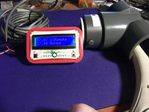
This photo shows the 228PV sensor connected to the prototype display. I am spinning the turbine with air from a heat gun.
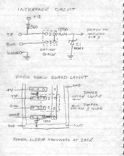
The electrical interface on the small flow meter has 3 wires, power, ground, and pulse output – relatively simple to connect to the microcontroller. But the large device has only 2 wires. It signals a pulse by shunting power to ground through a low resistance. The display must sense a pulse by looking for an increase in supply current. I designed an interface circuit that works with either unit by changing an option jumper. I constructed the interface circuit on a small piece of project board from Radio Shack (RIP). The positive supply feeds through a resistor which produces enough voltage drop when the large sensor is pulsing to trigger a digital low at the Arduino. The series resistor value is low enough that the power feed is still adequate for the small plastic sensor, so the option jumper just selects where to pick off the pulse signal. A series resistor and zener diode make sure the voltage ratings of the Arduino input pin are not exceeded. It’s a bad thing to overvolt an Arduino pin, please Don’t Ask Me How I Know This.
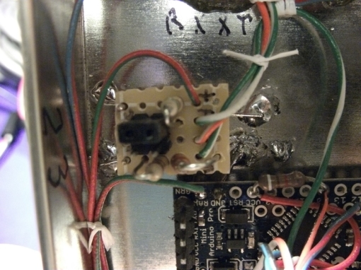
In this photo you can see the interface board soldered down near the front of the Altoids tin. I use “L” shaped bits cut from a paper clip, soldered to the board ground, and to the ground plane. The same technique anchors the Arduino board.
Physical Construction
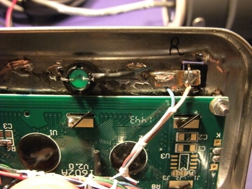
At first I worked up the circuit on a solderless bread board using code from the Adafruit web site. When satisfied with the results, I went ahead with building the Altoids tin prototype. The Arduino variant I used is a Sparkfun Pro Mini 5 Volt. It takes up little space and has a 5 volt regulator with enough capacity to run the 16×2 LCD. An LED and two push buttons protrude through the lid, these are regular 6mm square PCB buttons. I solder one side directly to the lid, the other side of the switch is supported by a bit of PCB material and a piece of paper clip wire.
This photo shows the LED and the Reset button. Note the bit of PC board on the high side of the switch has a groove filed across so the grounded paper clip is isolated from the signal connection.
This photo shows the Function switch. It’s hard to see, but there is a 0.05 ufd surface mount capacitor soldered between the signal side and ground. That capacitor is part of my debounce strategy.
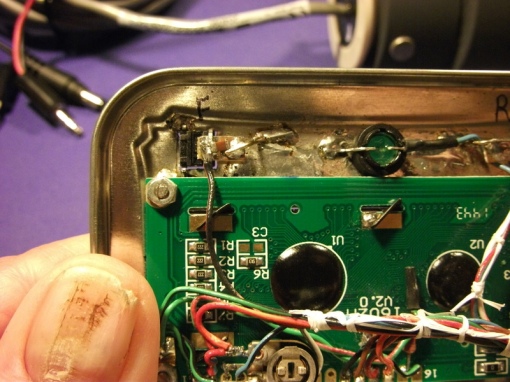
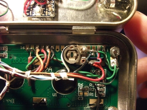
The Liquid Crystal Display itself mounts on four 2-56 screws. The screw heads are soldered directly to the lid. I attached a 10k Pot for contrast adjustment to the back of the LCD and it’s legs are used as tie points for 5v and ground wiring to the rest of the display.
If I have to build another one of these, I might glue the Arduino board to the back of the LCD which will greatly reduce the wiring between lid and box.
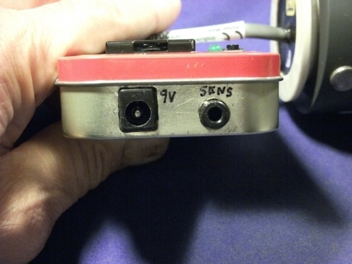
There is a power jack for 9 or 12 volt DC input, and a 3 conductor phone jack to connect the turbine sensor. These are epoxyed to the box. Connection to the sensor plug is as follows:
Ground to the plug sleeve
Positive lead to the plug tip
If the sensor is a 3 wire type, the pulse lead connects to the plug ring
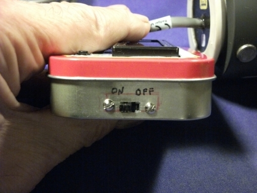
The opposite side of the box has a simple on/off slide switch mounted.
Software Considerations
Almost all of the turbine type flow sensors I looked at have two calibration factors specified: a “K” factor and an “offset”. During calibration the manufacturer measures the pulse rate outputs for a number of precise flow rates. These are plotted but since the turbine has some friction, the graph will not be linear especially at the low end and a linear regression is done to get a best fit straight line. The “K” factor represents the slope of the fitted line and has a dimension of pulses per unit volume moved. Offset represents the small amount of liquid flow required to start the turbine moving. You can assume that if any pulses are arriving at all, at least the offset volume of liquid is moving. The 228PV manual specifies:
Frequency = (Gallons per Minute / K ) – Offset
We are measuring pulse frequency so turning the equation around:
Gallons per minute = (Frequency + Offset) * K
In general, this formula applies to any measurement unit. It would be possible to convert a gallons display to liters by just scaling the K and offset factors by the constant liters/gallon. The Adafruit example sketch uses this method but measures pulse period in 1 millisecond increments which creates large gaps in the data if the pulse rate is over 100 Hz. At 200 Hz the pulse period will be 5 milliseconds, so a 1 millisecond period change is a 20 percent jump!
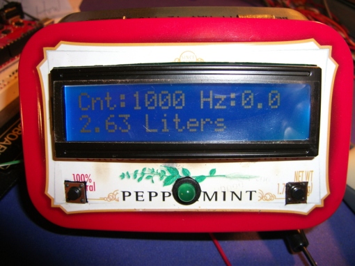
The following photo shows the display running Adafruit code:
Adafruit states their sketch is just an example to verify their sensors functionality but I felt higher accuracy at large flow rates was essential. An internet search turned up several sketches using a direct interrupt to count pulses. The sensor pulse train is applied to pin 2 or 3, fires on the rising edge of a pulse and calls an Interrupt Service Routine like:
void pulseCounter()
{
// Increment the pulse counter
pulseCount++;
}
Can’t get much simpler than that. Run this for exactly one second and you have counted pulses per second. Apply to the above formula and get volume units transfered in that second. Accumulate that many units each second to find total volume transferred. So the code to actually calculate rate and volume is easy. I exorcised most of the Adafruit code and added my own formulas. I also added a line in the ISR to blink the LED along with the incoming pulses.
Display and Operation
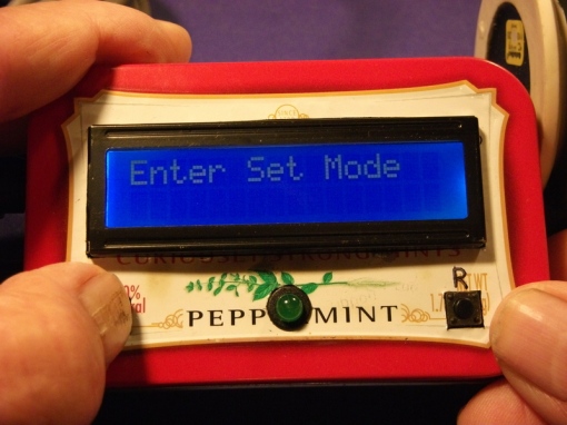
But this display needs to operate with multiple types of flow sensors. So I had to code an arrangement to set and permanently store K and Offset for whatever sensor was plugged in. That turned out to be the most complicated part of the sketch. I use the Function button to do this, taking advantage of the Arduino setup section which is only executed on a reboot. Holding Function down while resetting the processor starts set mode.
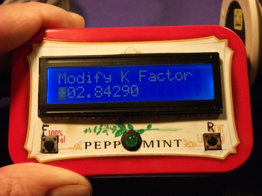
Releasing the Function button displays the stored K factor with a cursor flashing over the first character, the sign.
The Function button has three uses in set mode, depending on how long it is held.
A quick click increments the digit under the cursor
A press between 2 and 4 seconds advances the cursor to the next digit
A press greater than 4 seconds completes the setting and moves either to the offset setting or writes the data
To make this a little easier, I added code to blink the LED if the button is held between 2 and 4 seconds, and turn on the LED solid if held more than 4 seconds. I hope this is no more annoying than setting a cheap digital watch.
Note that K factors are always positive but occasionally a negative offset is specified.
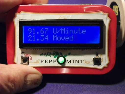
This photo is the normal running display entered after exiting set mode, or on a processor reset. The first line records units moved per second, where units is in whatever the given K factor uses. Both the Adafruit sensors have factors specified in Liters/Second. The 228PV I’m working with uses units of Gallons per minute. The water meter on my house here measures in cubic feet. You have to consult the sensor data sheet.
Resetting the processor zeros the cumulative quantity moved.
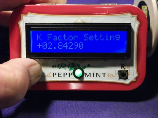
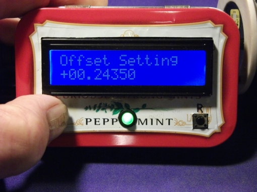
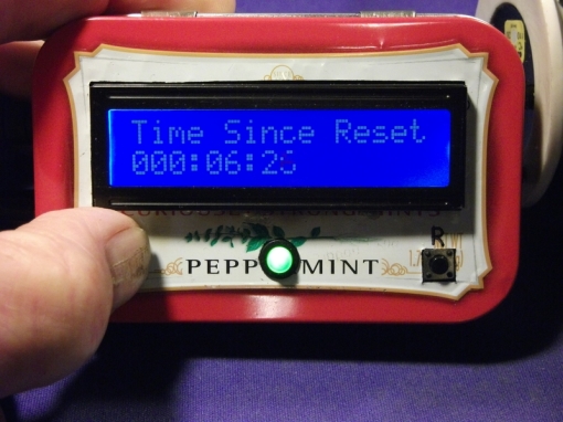
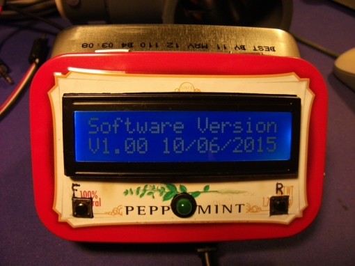
Finally, holding the Function button down during normal operating mode will cycle the following four displays:
The stored K factor
The stored Offset
Accumulated time since last reset. Note this is subject to the accuracy of the 16 Mhz clock in the Arduino.
A software version number.
Update October 25, 2015
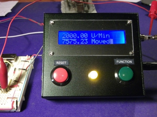
I’ve constructed a second unit. This one is built in a nice looking Extruded Aluminum box from Adafruit. I thought the better enclosure would make construction easier. I was wrong. Because it can’t be opened you can’t reach in and solder anything, and you lose the convenience of soldering anything needing a ground directly to the tin box. That means wires have to be attached to every terminal, brought to a common point and spliced. I did try soldering the Pro Mini to the back of the LCD and that works but the contrast pot had to be wired out so the assembly didn’t save much wiring. This photo shows the completed display with K factor set to 1.0 and a 2000 Hz crystal controlled signal applied to the sense input:
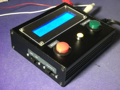
The left side has a power switch and also an SPDT switch for 2-wire/3-wire operation that replaces the option block in the prototype.
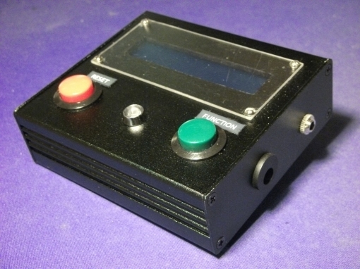
Sense in and power jacks are mounted on the right panel
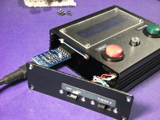
Have to open the left side to connect an FTDI Friend
Calibration and the K Factor
Most of these flow sensors will have specified somewhere in the data sheet, a K factor and offset. What the manufacturer does is plot flow in output pulses per second (frequency) against flow volume through the sensor at a number of flow rates. Then they do a linear regression on the data to get a best fit straight line. An example is Fig 1 in http://www.hofferflow.com/datasheets/miniflow2.pdf.
K factor is the slope of the line, usually given in pulses per unit volume, for example pulses per gallon. Offset accounts for the plot not being non-linear at the low end. Because of friction, it takes some small amount of fluid velocity to get the turbine to start spinning. You can assume that if the turbine is pulsing at all, at least the offset quantity is moving. Less than the offset volume is undefined. In the sketch, interrupt code blinks the LED when pulses are coming in.
There does not seem to be a standard for how K factor is presented. Sensors output a pulse stream at a frequency proportional to the flow volume as calibrated, this can be measured. With some sensors, you multiply the pulse frequency by the K factor to obtain a volume rate. Others however, require you to divide the pulse frequency by K.
In the sketch, I added a way to switch between these two methods by using the first character of the K factor. If this character is a “*”, the incoming pulse rate will be multiplied by the K factor, If the first character is “/” pulse rate will be divided by K. You may see a formula in the sensor data sheet like Freq = (Flowrate * K) – offset. Since we measure Frequency and need to display Flowrate, the formula is rearranged to Flowrate = (Freq + offset) / K and the K factor needs to be set to type “/”. Other sensors present Freq = (Flowrate / K) – offset. Rearranging that formula gives Flowrate = (Freq – offset) * K and you would set the K type to multiply, “*”. If the sensor documentation is not clear, just try it out. If the multiply/divide indicator is wrong, you will probably get totally unreasonable flows displayed. If so try changing the type indicator.
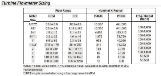
Here is a table from the FMC MNIT001 meter manual:
Note how K factors are presented in Pulses per Unit Volume. So for these meters, set the K factor type to “/”.
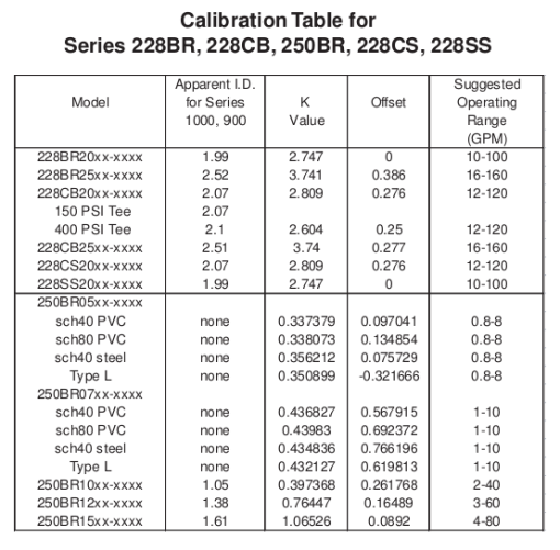
Another table, this one from Badger documentation:
Badger presents the flow frequency formula as:
So with these Badger sensors the rearranged equation to find flow rate is GPM = (Freq + Offset) * K and you would chose the multiply type option.
More information on the sketch’s K factor changes is in the file HERE_ARE_THE_DIRECTIONS.pdf included in the V1.10 dropbox download below.
Sketch and Revision History
The code can be downloaded from my DropBox account. I am carrying forward the original Adafruit license.
Version 1.oo Oct 08 2015 Initial release
http://dl.dropboxusercontent.com/u/40929640/FlowMeter/flowmeterV1.00.zip
Version 1.01 Oct 17 2015 Correct schematic error
http://dl.dropboxusercontent.com/u/40929640/FlowMeter/flowmeterV1.01.zip
Version 1.10 Oct 25 2015 Change method of applying K factor
https://www.dropbox.com/s/73jaqmua52j9wp3/flowmeterV1.10.zip?dl=0


Hi
I want to build this device, and I would like to be ensure that the count is not lost if the power is lost.
I want to write to EEPROM when the Arduino detects power down – I’m not sure it is ok… because EEPROM cycle use is limited.
Could you help me?
If you detect power down it’s too late to write and writing EEPROM is relatively slow. So you need to write the reading on a timed basis, say every 30 seconds. So to get around the 100,000 write limit, you could spread the readings out over the memory area. I would write the reading plus a time stamp, probably need four bytes each so no problem saving 32 of those in different EEPROM locations which would multiply the 100,000 by 32. On power up read through the 32 data pairs and restore the one with the latest time stamp. Some discussion at http://www.avrfreaks.net/forum/avr-eeprom-life-endurance
Hello,
Very interesting project and especially the part with the Function button and the change of K factor in the Arduino setup section.
Could you please upadate the above link in Dropbox for the code because it doesn’t seem to work.
Thank you.
Ah, Dropbox changed the way they do public files, I have to redo every single link in every page I used them to store files. Try the download now, it should be fixed. Please let me know if it doesn’t work.
Thank you very much for the prompt response! It’s working. Searching around the internet for flow sensors with Arduino i came across with a lot of tutorials but your explanation and the covered aspect of K factor, is very remarkable.
I am looking forward to study your code!
Thank you, I hope I got it right. K factor is mysterious. I researched on the internet a lot and never did find a firm definition of what it was and how it was determined from tests. The fact that some sensors have a negative K factor tells me it’s not completely understood.
Very good project! Even though your code is well explained my knowledge in Arduino programming environment prevents me to fully understand the code, hoping for your help.
The purpose of the below call by reference function, is to assemble a floating point number from an array which is stored in eeprom.
void printDigits(char *Digits, float *floater) {
// reassemble the floating point number from the stored character array
*floater = atof(Digits + 1); // Skip the first character
lcd.setCursor(0, 1); // Move to second LCD line
if (Digits[0] == ‘-‘) { // Type was ASCII minus
*floater = -(*floater); // If -, negate the argument
}
lcd.print(Digits); // Print so it looks like a real number
lcd.print(” “); // Erases the rest of second line
The pointer ( *Digits ) is the value at the address of the elements of the the array Digits( you use it for KDigits[])
The pointer ( *floater) is the value at the address of the float variable floater ( you use it for K variable)
With this line of code *floater = atof(Digits + 1); you convert the array characters to a float number.
With this line of code lcd.print(Digits); what do you do?
Why do you print the address of the elements of the array Digits (if i have understand well) and not the floating number *floater??
Furthermore, when you use the function printDigits(Kdigits, &K) should you use &Kdigits instead of Kdigits?
Thank you!
I have not touched that code in five years but will try to answer. In C using just the name of an array is automatically the address of the array. Arduino print recognizes that and prints the referenced array. float *floater in the function call passes back the ascii number converted to a float.
// Test program to exercise printDigits function
void setup() {
// put your setup code here, to run once:
char KDigits[10] = {“-1234.5678″};
float K = 0.0;
Serial.begin(9600);
delay(500); // Teensy needs this
KDigits[9] = 0x00; // Ensure a valid string terminator
Serial.print(K); Serial.println(” K initial”);
printDigits(KDigits, &K);
Serial.print(KDigits); Serial.println(” KDigits as ASCII”);
Serial.print(K); Serial.println(” Float K passed back”);
}
void loop() {
// put your main code here, to run repeatedly:
}
/********************************************************
Formats and prints the ASCII parameter array to LCD
Passes back an assembled floating point number
********************************************************/
void printDigits(char *Digits, float *floater) {
// reassemble the floating point number from the stored character array
*floater = atof(Digits + 1); // Skip the first character
// lcd.setCursor(0, 1); // Move to second LCD line
if (Digits[0] == ‘-‘) { // Type was ASCII minus
*floater = -(*floater); // If -, negate the argument
}
// lcd.print(Digits); // Print so it looks like a real number
// lcd.print(” “); // Erases the rest of second line
Serial.print(Digits); Serial.println(” Digits as ASCII”);
}
Thank you!! I think this is the answer.
“In C using just the name of an array is automatically the address of the array. Arduino print recognizes that and prints the referenced array”.
If you do the same for variable you have to use *pntr for the value and &var for the adress.But for the arrays “the name of an array is automatically the address” and “Arduino print recognizes that and prints the referenced array”. So you don’t need to use * and &.
i had read various tutorials about pointers but know i realized that it was about a pointer to variable’s address only.
Pointers are easy to understand but difficult to use. It usually takes me a dozen trys to get what I want.