Sand Clock – 2024 (this post is in progress)


Genesis
In mid-2023 my Brother in Law asked me what I would like for my birthday. After some back and forth I sent a list of Adafruit parts with which I could construct a second digital clock based on the design and software from my initial effort in 2022 (see “A Clock With Benefits“). The Adafruit parts would be slightly cheaper. I offered to gift him the clock for his 2024 birthday.
Adafruit Matrix Portal S3 #5778
Adafruit 64×64 RGB Matrix Panel #5362
Adafruit 5V, 4A Power Supply #1466
Adafruit DS1307 Real Time Clock #3296
The project required other small parts most of which I had on hand. Adafruit was out of stock on these major parts so did not have everything until November – which was a bad month for me due to medical issues. So the port started in December 23. I had a nice piece of beautiful 1″ Padauk which was resawn and milled into 5 1/4″ x 2 1/2″ x 3/8″ pieces to make a case for the new clock. A bit of salvaged plywood made the back panel and the front panel is smoked plastic diffuser (Adafruit #4749)

My circa 2022 clock used a PJRC Teensy 3.6 with a Smart Matrix shield from Pixelmatix. I thought software written for the Teensy would easily port over to the Adafruit Matrix Portal. I was wrong. The biggest problem was that Smart Matrix libraries used a three byte 8bit-8bit-8bit RGB method to represent colors. Adafruit’s libraries use a 5bit-6bit-5bit RGB scheme all packed into a sixteen bit integer variable. Also Adafruit has no method for globally changing the brightness of the display. Smart Matrix makes that easy but for the S3, I had to write my own procedure for adjusting brightness as the clock running full song was annoyingly bright in a dimly lit room. I will outline my method later in this post as it may be useful to someone else.
In 2022, the Teensy 3.6 had a Real Time Clock built in but no acceleration sensor. I used an Adafruit LIS3DH sensor glued to the back cover. The Matrix Portal board in this years version has a built in acceleration sensor but no Real Time Clock. I used an Adafruit DS1307 clock. It is mounted directly under the Matrix Portal board.

I am not using any of the wireless capability of the Espressif ESP32 processor on the Matrix Portal S3 board. That’s above my knowledge level at this time. The S3 chip proved to be surprisingly brittle and the Arduino IDE produced code crashes a lot. Simple things like adding a delay() or Serial.print() to the sketch would sometimes cause the software to crash all the way back to the boot loader. Debugging was difficult under these conditions and I would not recommend using the Adafruit Matrix Portal S3 under Arduino IDE until Espressif does something about this. I am running ESP32 library 2.0.15 and Arduino IDE 2.3.2. Note: Espressif is showing a scheduled update to version 3.0 in April 24.
2024 Clock Operation
Here are all the screens available on this version. Some have changed from the 2021 code and some have been added. There are now sixteen options in the setup menu. To enter Setup Menu mode, press and hold the Function button for three seconds (a long press). You can then scroll through the screen options using the Up or Down buttons. When the desired screen is listed, a half second press on Function (a short press) will select and start that mode. Two of the screens, Brightness and Clock Set have settings that are manipulated using the Up or Down buttons.
This is the basic clock display that started the whole project. A straight forward digital 12 hour display. It also has the Sand Nature, when activated by shaking the clock three times in two seconds the display will turn into digital sand which can be poured around the screen by tilting the clock. Sand is displayed for 30 seconds then fades back to the clock. Pressing the Down button will return a sand display to the clock screen immediately.

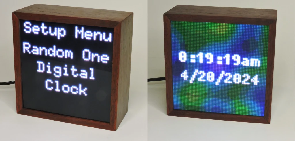
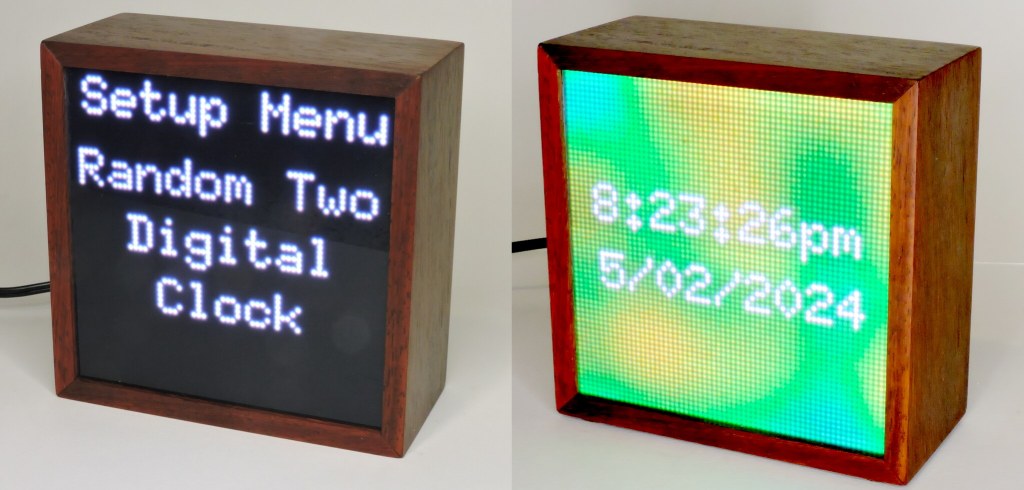
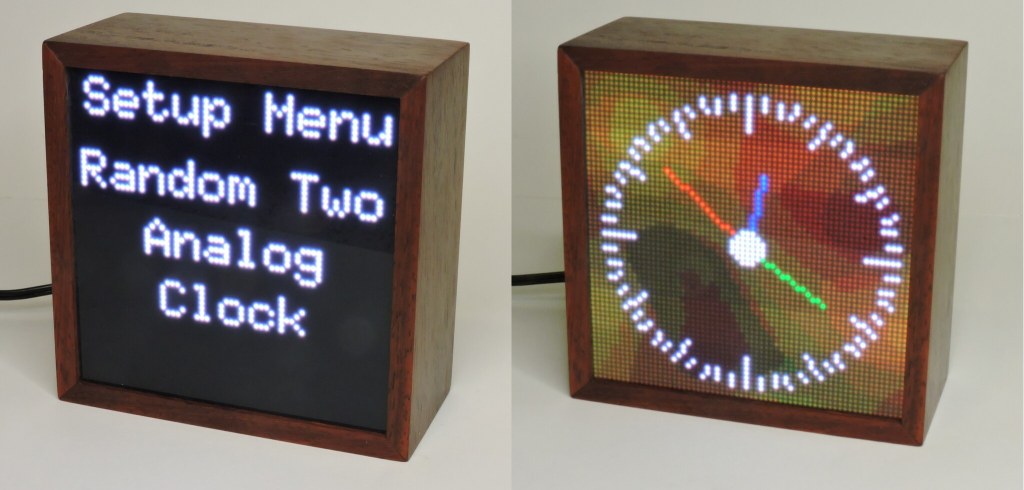
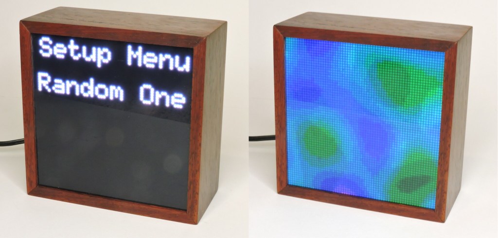
The software can also generate a slow soothing background for the Digital display. Two different backgrounds are selectable, Random One is more bluish, Random Two has warmer colors. These screens do NOT have the Sand Nature.
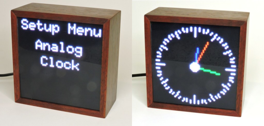
An Analog Clock is also available for those who prefer Retro time keeping. The bare Analog Clock also has the Sand Nature when shaken, which can be cancelled by pressing the Down button. It was based on code posted to Hackster.io in 2021.
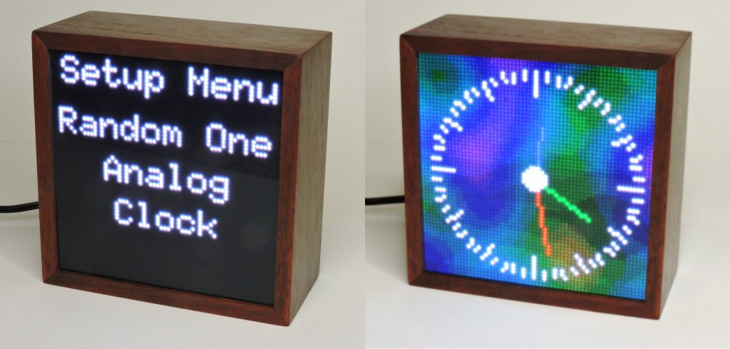
Similar to the Digital Clock, the Analog version has two colorful changing backgrounds available.
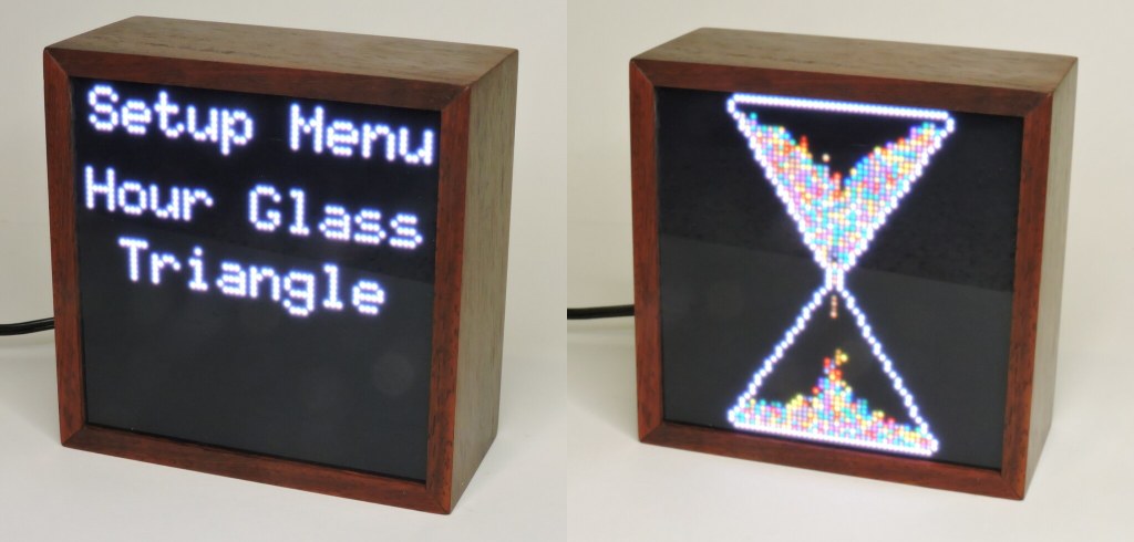
Next, for those who REALLY need Retro time keeping there are two hourglass screens. They differ in the shape of the simulated container. Triangle Hourglass empties in about 50 seconds, the rounded version in about 90 seconds. These can be reset by a press on the Down button.

If you just want something soothing, two screens are available showing only the slow changing color display used in the clock backgrounds. These backgrounds are adapted from the Noise demo sketch included with the FastLED library.

The next menu item is a Magic Eight Ball simulation. If you are of a certain age you may have had one of these to help make life’s decisions. It is a billiard 8 ball filled with thick fluid. There is a window and multi sided dice floating inside which allow a random phrase to appear in the window. This toy is still made and sold by Mattel.
A random response is triggered when the clock is shaken. A hand full of digital sand is thrown in just to make the display more interesting. Pressing Down will reset the display.

The clock has two slightly different implementations of John Conway’s Game of Life, beautifully coded by Jason Coon. If you are not familiar with Conway’s Game, I highly recommend reading the fascinating Wikipedia article. Conway simulates cellular growth through multiple generations (think bacteria on a Petri Dish). There are only four rules:
- 1. Any live cell with fewer than two live neighbours dies, as if caused by loneliness.
- 2. Any live cell with two or three live neighbours lives on to the next generation.
- 3. Any live cell with more than three live neighbours dies, as if by overpopulation.
- 4. Any dead cell with exactly three live neighbours becomes a live cell, as if by reproduction.
A game runs for one minute then automatically resets. Pressing the Down button will reset the display immediately. Pressing the Up button will buy another 30 seconds of run time in case something interesting is going on. The two selectable versions differ only in the Blur option. If Blur is selected, Every other run has the display blurred a bit.

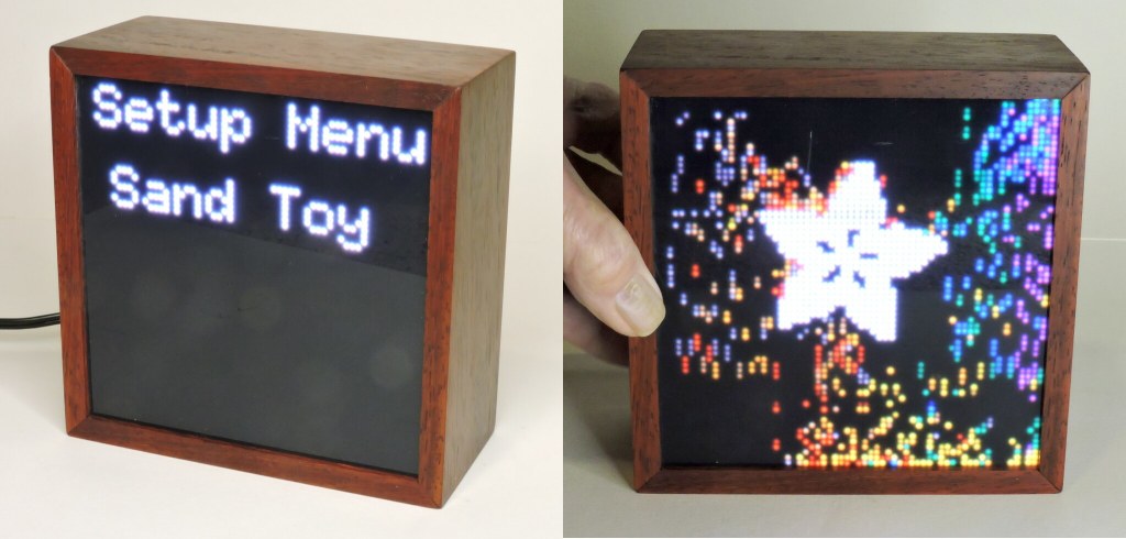
The last variation is Sand Toy. It just puts up some digital sand to play with. There is an Adafruit logo planted in the middle that has blocking set so the sand will not run over the logo. Sand Toy will reset if the Down button is pressed.
Brightness and Setting the Clock
These final two setup options bring a user to a second screen with settings options.
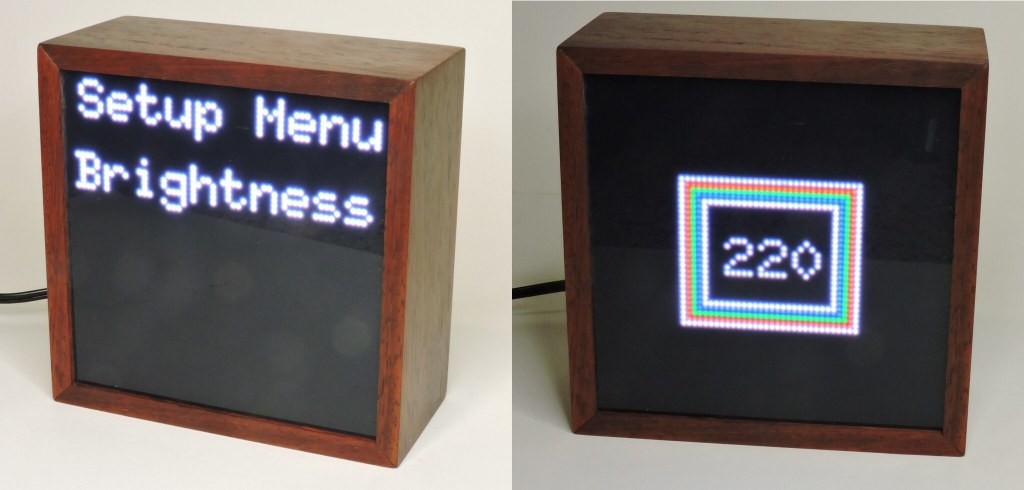
Selecting Brightness setup takes you to another screen which has the ability to change how bright the LED display is. Use the Up/Down buttons to change the value, you will see the effect in the colored squares surrounding the Brightness number. The range is 10 to 255 and to speed things up, the number changes in steps of ten. Short press the Function button to make the change permanent, then long press Function to exit the Brightness screen. Then you can move to any of the other clock menu items.
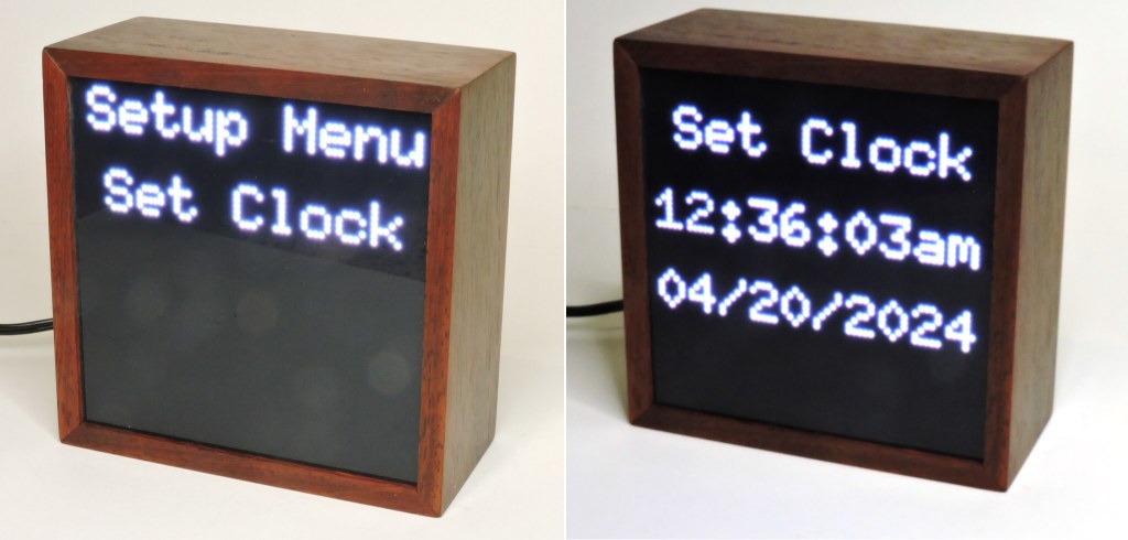
Finally there is the Clock Setting option. Seven fields are changeable. Hour, Minute, Second, AM/PM, Month, Day, and Year. You move from field to field with a short press on the Function button after which the Up/Down buttons can be used to change the number. A long press on Function writes the settings into the clock chip and returns to the Setup Menu.
Software
All software was written via Arduino IDE, currently version2.3.0. The environment is C++ though it is cut down to vanilla C. Much of the Clock is based on demonstration programs which usually come with the libraries. Several Adafruit Arduinoish libraries are used though Adafruit puts most of it’s development effort these days into Python, which I have not yet embraced. Python was not as prevalent in 2022 when I made the first clock, and for this effort I wanted to reuse as much of that code as possible. The sketch is a mashup of code I wrote, code lifted from library examples, and code lifted from the Adafruit learn guides. Some of the modules were adapted to the Matrix Portal S3 with 64×64 LED panel separately as a debugging exercise. These sketches are in the Finished_Demos directory.
I promised to discuss my method for globally changing screen brightness. The method relies on the sketch using fixed tables of color which is the case for most of the Adafruit libraries. Tables sometimes are specified in an array of 565 colors like:
- colors[0] = matrix.color565(64, 64, 64); // Dark Gray
- colors[1] = matrix.color565(120, 79, 23); // Brown
- colors[2] = matrix.color565(228, 3, 3); // Red
- colors[3] = matrix.color565(255,140, 0); // Orange
- colors[4] = matrix.color565(255,237, 0); // Yellow
- colors[5] = matrix.color565( 0,128, 38); // Green
- colors[6] = matrix.color565( 0, 77,255); // Blue
- colors[7] = matrix.color565(117, 7,135); // Purple
or separately like this:
- #define BLUE 0x001F
- #define RED 0xF800
- #define GREEN 0x07E0
- #define CYAN 0x07FF
- #define MAGENTA 0xF81F
- #define YELLOW 0xFFE0
- #define WHITE 0xFFFF
These end up as 16 bit unsigned integer variables with the Red, Green, Blue numbers packed as five bits Red, six bits Green, and five bits Blue sometimes typed as color565. You can’t just multiply one of these by a fraction, you have to multiply each component color separately.
My approach was to specify a fixed set of reference colors as three byte RGB equivalents in a header file (rgbColors.h). The Brightness function then on request multiplies those RGB values by a desired fraction and converts the scaled 8,8,8 result into a 5,6,5 sixteen bit working table inside the sketch. Any sketch process using color tables will access the internal working version which can be changed at any time by invoking the Brightness function. ESP32 does have a floating point processor so this method works quick enough to program a smooth fade out of the digital sand and fade in the clock screens.
Another issue I found early on is the ESP32 will not start if the program is expecting a serial port and it doesn’t find one. I set a tag variable at the beginning and checking for it’s existence, enable or disable all Serial functions. This allows debugging with Serial but commenting out the variable will let the ESP32 start up when the USB-C is not connected. Every instance of Serial.print must be wrapped with #ifdef serPort and #endif.
Variable setup:
// Matrix Portal will not start if it’s looking for serial port so
#define serPort // Comment this line out if not using Serial.
Using the serPort tag later:
// Initialize LED matrix…
ProtomatterStatus status = matrix.begin();
#ifdef serPort
Serial.print(“Protomatter begin() status: “);
Serial.println((int)status);
#endif
Hardware Issues
There is the afore mentioned tendency to crash back to the bootloader. Unknown at this time if this is a hardware, firmware or software issue.
The ESP32 S3 requires a two button press sequence to put the chip into software upload mode. Then a button must be pressed to start the sketch. This is a PITA when have fat fingers and you’re debugging and uploading 10-15 versions per hour. It also means you have to open up the box to update the load as adding external pushbuttons and an external USB jack is a bad idea.
The Adafruit pushbutton switches I used for Up/Down/Function bounce horribly sometimes causing an intended selection to be skipped. I have a function to reliably read cheap pushbuttons but it depends on using analogRead on the button. I found analogReads on the ESP32 take 10 milliseconds which was limiting the clock frame rate to about 30 FPS. Switched to digitalRead and read time dropped to 6 microseconds, the frame rate increased to about 55, much more acceptable.
We bought the same part number 5362 64×64 LED matrix as I used in my 2022 Teensy version. The display looked way off and it turned out the LED panel was wired differently. See this post:
https://forums.adafruit.com/viewtopic.php?p=997072&hilit=5362#p997072
Apparently the HUB75 protocol does not specify which channels connect to which colors and many people have reported this issue especially with LED panel purchases direct from China. In my source code package, there is included in the “Finished_Demos” directory a program “Noise_Demo” which starts up with full screens of the six primary color choices, Red, Green, Blue, Cyan, Magenta, and Yellow. Running this sketch should immediately point out anomalous wiring in your panel. The fix is simple. Since assigning color output pins is part of the initial setup, just rearrange the assignments to correspond with your matrix panel. There are two sets of pins that must be changed:
// Matrix purchased in 2023 has red – blue switched
// PinOrder is upper-half red, green, blue, lower-half red, green blue
//uint8_t rgbPins[] = { 42, 41, 40, 38, 39, 37 }; // Original
uint8_t rgbPins[] = { 40, 41, 42, 37, 39, 38 }; // Red, Blue swapped
Hello, I got a RSS-Update SandClock2024. But is there an update?
Is in progress, I needed to establish the URL.