Automating the Box Joint Jig Lead Screw
I constructed an Arduino based controller to automate the carriage on my lead screw Box Joint Jig which was originally inspired by Matthias Wandel at woodgears.ca. Interestingly, Matthias added automated operation by a laptop to his design at the beginning but later removed the function in favor of multiple wooden gear sets. My jig was manual at first and automated later after I kept losing count of the crank turns
See this WordPress Blog entry on construction of my Box Joint Jig and also this Blog entry on some of the applications.
A video of the development breadboard in action is at www.youtube.com/watch?v=6Zz1fGDO5jw.
A video of the controller installed on the jig and working is at www.youtube.com/watch?v=URk4qYnEWgI
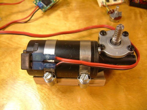
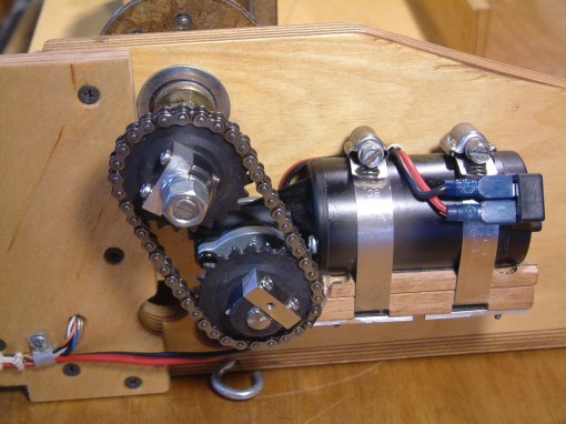
I used an inexpensive DC motor driven with a Polou MD01B H bridge, and added position feedback to the lead screw. This gear drive motor from All Electronics (DCM-697), was intended for actuating automotive power seats. I sawed the shroud off the connector housing so I could use standard push on terminals. The mounting base is a bit of hardwood flooring rounded out to fit the motor and hose clamped on. I can loosen the clamps and slide the motor to align the sprocket and adjust the chain.
This shot shows how the lead screw shaft has been cut and ground down to fit the "D" shaped hole in the drive sprocket.
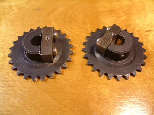
Two 24 tooth sprockets from All Electronics (GR-100). They don’t come with a cap for the shaft collar so I made some from a piece of aluminium. Normally they have a “D” shaped hole. The sprocket on the left has it’s D intact – it will go on the motor shaft. The sprocket on the right has it’s D filed out round so it can clamp on the 3/8 threaded rod that drives the Box Joint Jig. I have since replaced the motor side sprocket with a 42 tooth part to speed up the carriage motion.
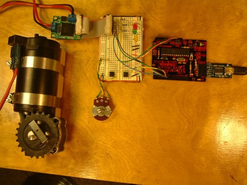
Photo of the first test bed. Power seat motor on left, Pololu motor driver (MD01B) above that, protoboard in the center and Arduino on the right. Two buttons on the protoboard run the motor either CW or CCW. The amazing little Pololu board has a VNH3SP30 H bridge chip which is less than 3/4 inch square but can switch 30 amps!
Since the motor is a simple series type, I need a way to inform the Arduino how far the shaft has rotated. An optical sensor could be used but then there would be sawdust issues. Instead I use a Hall Effect sensor and permanent magnets.
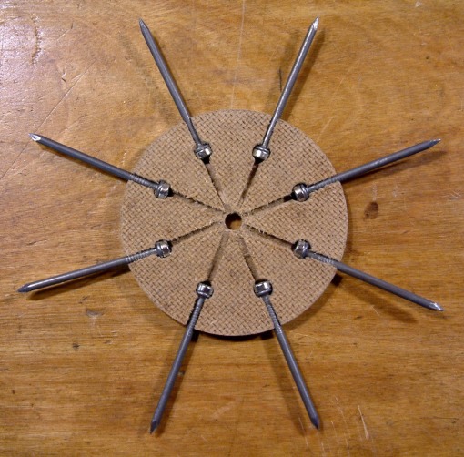
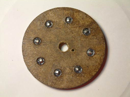
This is the prototype position disc. It will go on the jig’s lead screw. Quarter inch button magnets are coupled to six penny nails to focus the magnetic field and pressed into slots sawn in the disc.
Here the magnets and nails have been epoxyed and a coat of varnish applied.
This was intended to be a prototype but performs well enough that it probably will be the final. The disc is 3 inches in diameter and will be taped directly to the motor sprocket for software development purposes.
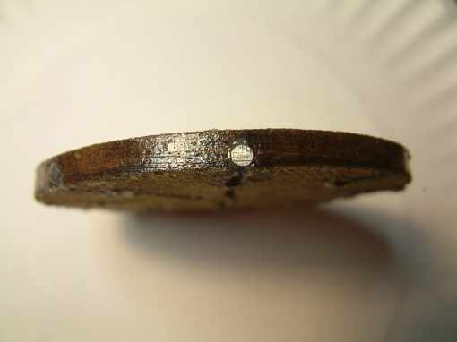
Detail of the disc edge showing one of the six penny nails sawn off and filed flush.
The Hall Effect sensor (SS441A from Jameco) gives a clean transition when placed about a quarter inch from the edge of the disc. NO bounce observed (Yay!) so I can easily code an interrupt driven counter. Eight steps per rotation on the 16 TPI shaft will give a resolution of 0.0078125 inch at the carriage. One – One Hundred Twenty Eighth of an inch.
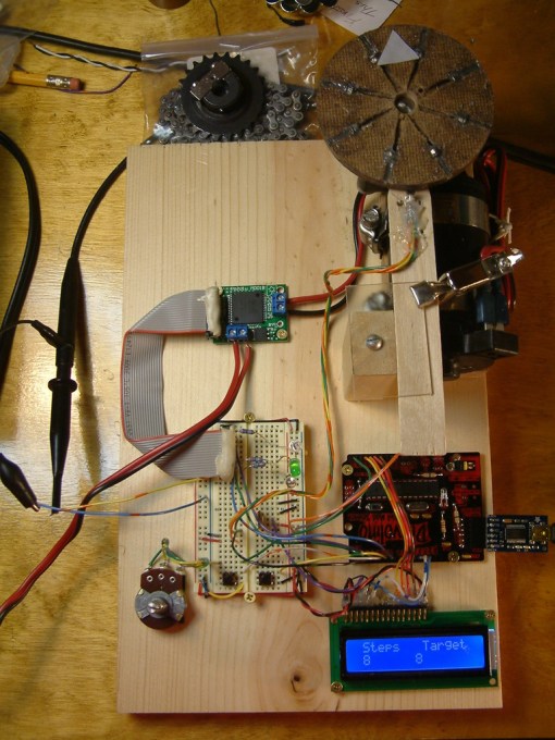
Since this is the Breadboard phase of development, I thought it appropriate to mount the parts on a real board. At this point the motor software is done but the menus are not. A video of the development breadboard in action is at www.youtube.com/watch?v=6Zz1fGDO5jw.
Clockwise from the top:
– Chain and sprocket for the lead screw
– Sensor disk temporarily on motor
– Motor and mount screwed down now
– Hall Effect sensor glued to a stick
– Stick clipped to mount so its adjustable
– Arduino clone board
– 16×2 LCD display
– PWM pot (not used, will be removed)
– Proto board with LEDs and buttons
– MD01B motor driver
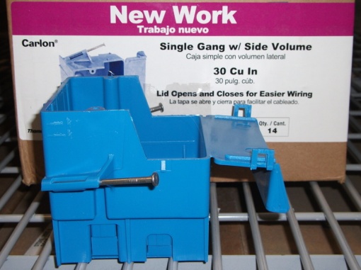
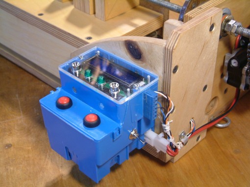
Here is the box I selected to hold the completed controller. It is a standard electrical box from Lowes, but it has a bump out on one side that forms a nice surface on which to mount button switches. The lid of the bump out is molded as part of the box. You fold it over and it snaps on. You can do this about 3 times before the plastic hinge breaks off so plan the layout carefully beforehand. 30 Cubic Inches sounds like a lot until you start stuffing cables in there.
I amputated the 8 penny nails and mounting ears. LCD and LED indicators mount flush on the top where the AC receptacle would normally be.
I think the box has enough holes now…. Putting the controller hardware into the box is more complicated than it seems. Just the box itself needs wires from two buttons, power switch, 12 volt feed, motor feed, two limit switches, and the Hall Effect sensor.
Outside, a blue Euro style block is glued on for the Hall and limit wiring, Two pin Molex connectors added for the 12 volt leads. The box material is soft enough that it cuts easily with a utility knife.
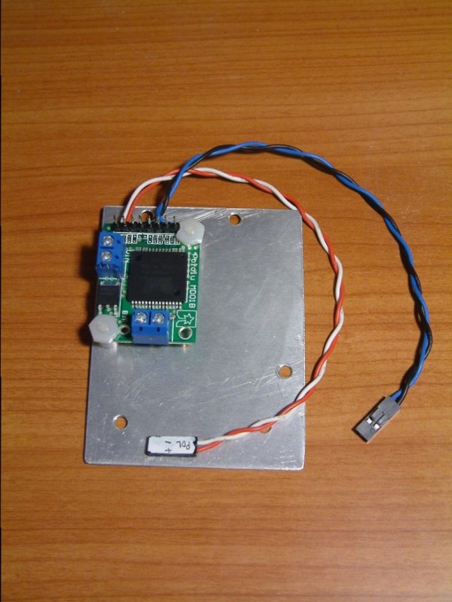
Here is the Pololu MD01B motor driver in it’s new home. Have to use plastic screws because the plating around the mounting holes is electrically hot (why??). This small sheet of aluminum fastens inside the box via the two countersunk holes visible just above the buttons in the previous photo.
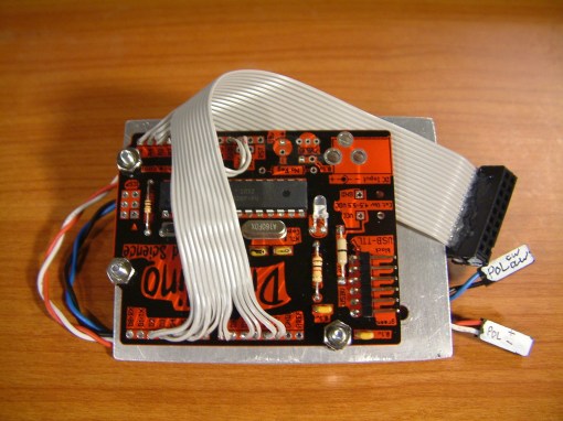
The Arduino clone processor is mounted on the opposite side of the aluminum plate. Four analog inputs and 12 digitals are cabled out.
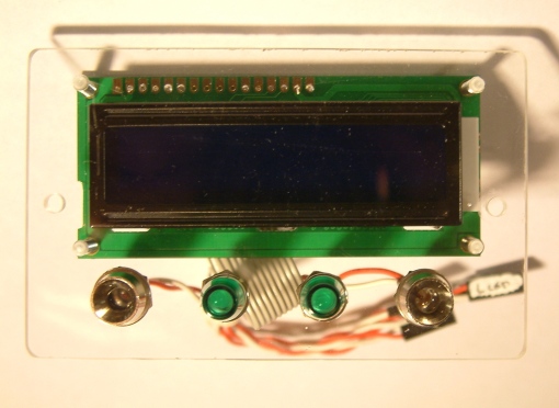
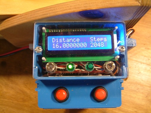
Four LEDs and the 2×16 Liquid Crystal display are mounted on a piece of plexiglass cut to fit the top opening of the box.
Leds are:
slewing left
power on
hall sensor (added for coolness factor)
slewing right
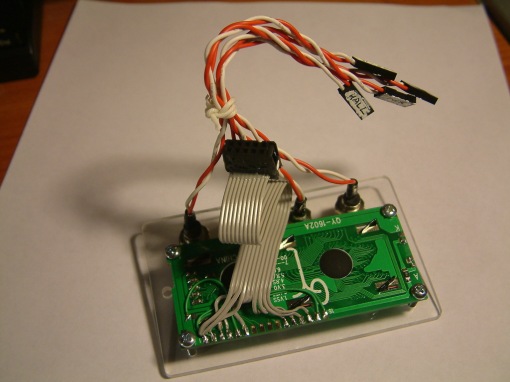
This is the display panel seen from the bottom. Four 2 wire connectors for the LEDs and a 10 wire cable for the LCD display.
The small connectors are salvaged from PC front panel displays, the multi wire connector is sawn off an IDE hard drive cable.
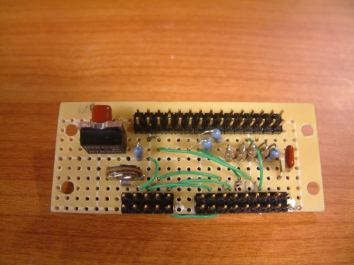
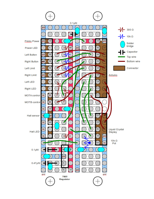
I used a Radio Shack PC board to make a central interconnect for all the buttons, limit switches, LEDs, Hall sensor, LCD display, and processor. There is a 5 volt regulator for the logic side, pullup resistors and LED dropping resistors. This cries out for a printed circuit board but since I’m only building one of these, it will do as is. I would have to work through this stage to design a PC board anyway.
Made a drawing of the interconnect board so I could remember where things plug in.
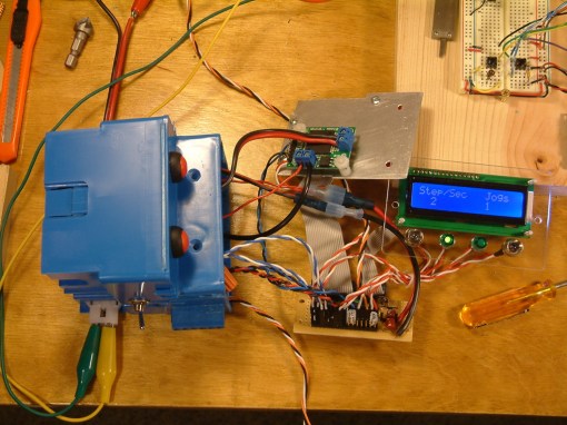
Final mock up to test wiring. All this has to go into the blue electrical box. Found two LEDs functionally reversed. One of the cool things about the Arduino is the pins are software defined so that took maybe a minute to fix in software. The 5 volt regulator got too hot for comfort so in a last minute change, I moved the regulator chip over onto the aluminum sheet – even more wires!
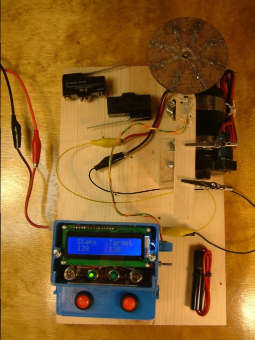
Well it does all fit, though it’s a PITA to find a place for all those wires. This shows the completed controller connected to the breadboard motor mount having just made a 128 step (1 inch) simulated slew, sixteen revolutions of the sensor wheel. Those two microswitches will be limit switches on the jig, and I will use an inline fuse in the 12 volt feed, couldn’t find room inside.
This shows the motor screwed to the end of the jig, two sprockets, and #25 chain. These parts came from All Electronics.
It sticks out more than I hoped. Maybe need some kind of guard to keep fingers out of the chain.
I made a small L shaped plywood structure for mounting the controller on the box joint jig. The mounting is tall enough to protect the sensor wheel assembly and the right limit switch.
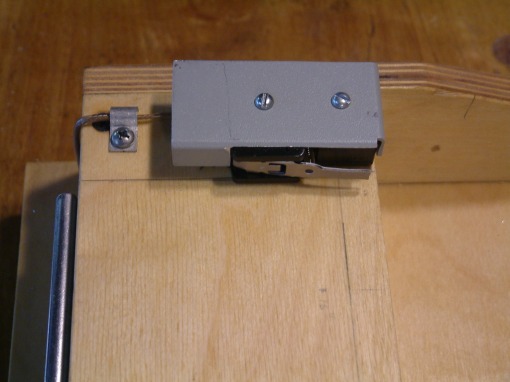
Mounted the left hand limit switch horizontally. It is very exposed so I cut off most of the actuating lever and made a guard out of aluminum.
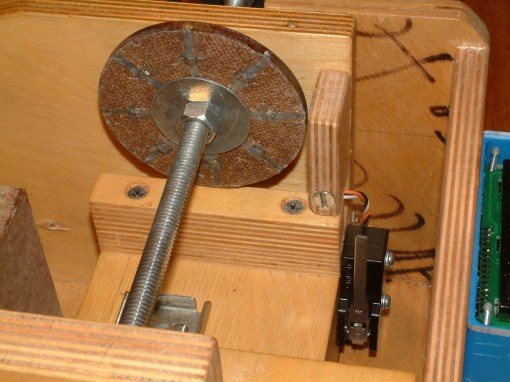
This photo shows the sensor wheel mounted on the lead screw shaft. The Hall Effect sensor is epoxied into the small wood block just right of the wheel. It gave me grief, it didn’t work! After a lot of experimenting, I determined the Hall sensor is only sensitive on one side. I had glued it into the block upside down. Turned it over and success! You can also see the right limit switch mounted vertically.
I set the controller to slew sixteen inches. Ran it up and back about ten times, it always came back to the exact same spot. Takes more than a minute to go 16 inches. I will look for different sprockets to speed it up. The motor has plenty of torque, I put most of my weight on the carriage and it didn’t slow down a bit. I’m using an XBox power pack to supply 12 volts, it’s easily up to the job, but wish I could figure out how to get it up to 15 volts.
A video of the controller installed on the jig and working is at www.youtube.com/watch?v=URk4qYnEWgI.
Arduino source code can be downloaded from Dropbox here.
Completed Box Joint Projects
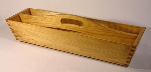
A Roy Underhill Memorial Tool Tote. About 30″ long, 9″ wide. The yellow pine does not seem to take an oil finish well.
The box (finger) joints all cut on the automated lead screw jig.
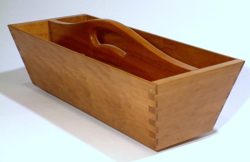
Another smaller tool tote done on the automated jig. This example in Cherry.
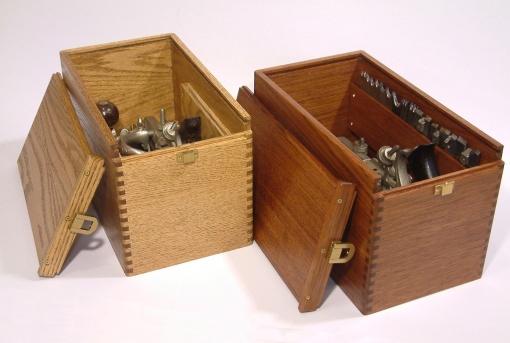
These boxes made for my two Stanley 45 Combination Planes.
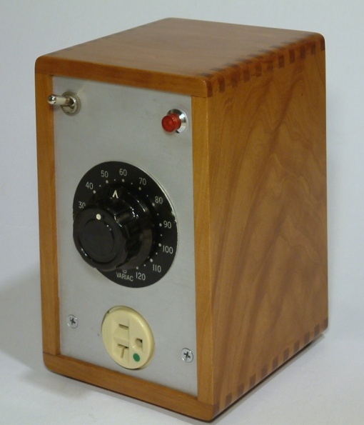
I made this to hold a small Variac transformer. Keeps my soldering iron at just the right temperature.
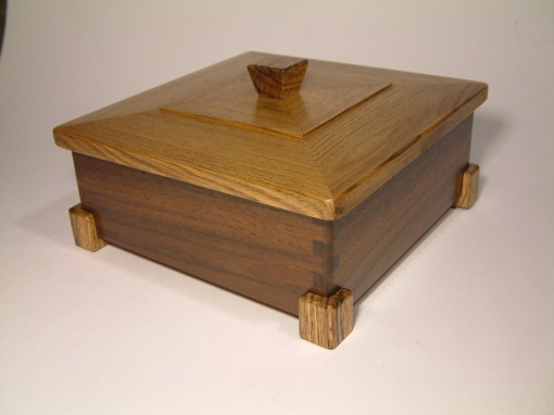
This Walnut, Butternut, and Oak box was made for my Brother-in-Law.


This is amazing. I had the same thought and was going to tackle it after the holidays. Now I have a resource to check out.
I was also inspired by Mattaisis’ projects.
looking for source code
Nice Project
https://dl.dropboxusercontent.com/u/40929640/BoxJointAutomation/BoxJointAutomation08.zip
Code is very messy. Was only my second Arduino project. If I did it over, I would add a third button to do menu selections. The method of pressing both buttons simultaneously to select gave me a lot of trouble.
Me too.